Ta x – XTA DS8000/D User Manual
Page 12
DS8000 Operator’s Manual
Page 12
ta
x
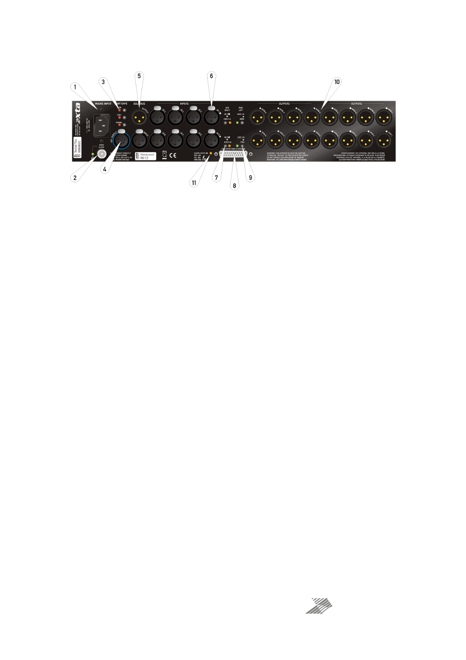
Rear Panel Controls and Sockets
1: Mains input socket: Supply voltage is 100-240V AC. This unit must be earthed.
2: Word clock and Lock LED: This BNC socket (when ADC option fitted) can provide either a
word clock output or input, dependent on the ADC jumper setting). Please see the ADC option
set-up, starting on page 18.
3: 48V safe switches: These switches allow the disabling of three different 48V controls.
If the “MON” safe switch is enabled then sensing of phantom power via all MON output
sockets will NOT enable on 48V on the inputs.
If the “FOH” safe switch is enabled then sensing of phantom power via all FOH output sockets
will NOT enable on 48V on the inputs.
If the “PANEL” safe switch is enabled then pressing a “48V” switch on the front panel will
NOT enable on 48V on the inputs. Note the LED by the respective 48V will still illuminate,
even though 48V is not sent to the input socket.
4: Ext. supply socket: Two units can be connected together via a 5-pin to 5-pin XLR cable
(wired 1-1) so that, in the event of either unit losing its mains supply, the other unit can power
both. Further notes on this feature are given on page 10.
5: Solo bus input/output sockets: The solo bus is externally accessible via these sockets,
allowing multiple units to share the bus. When units are “daisy-chained” using this bus,
plugging headphones into any unit will provide monitoring of any input channel, without
needing to move the headphones from unit to unit.
6: Input XLR sockets: The input channels are electronically balanced and accept signals up
to +26dBu. They have a high input impedance of over 10k ohms so will not “load” microphone
signals which can lead to dulling when combined with long cable lengths. For more on this
topic, see the section at the end of this manual starting on page 26.
7: O/B split switches: To provide more outputs from a single input, rather than have to
connect the output of one channel back into the input of another (and in the process, sacrifice
performance by having to route some channels through cascaded preamps), this can be
performed internally by pressing one of these switches. Input 1 can be routed to drive all
outputs on channels 1 to 4 (so providing a 1 to 16 spilt), and input 5 can split to all outputs on
channel 5 to 8. Note that the meters on “slave” channels will show the same reading as the
“master” channel, and the gain controls on the slave channels won’t adjust their respective
output levels.