Ta x, Disabled – XTA DS8000/D User Manual
Page 14
DS8000 Operator’s Manual
Page 14
ta
x
-10dB
-10dB
0dB
0dB
-10dB
-10dB
0dB
0dB
INPUT
CHANNEL 1
INPUT
CHANNEL 2
INPUT
CHANNEL 3
INPUT
CHANNEL 4
INPUT
CHANNEL 5
INPUT
CHANNEL 6
INPUT
CHANNEL 7
INPUT
CHANNEL 8
OUTPUT
CHANNELS 1
OUTPUT
CHANNELS 2
OUTPUT
CHANNELS 3
OUTPUT
CHANNELS 4
OUTPUT
CHANNELS 5
OUTPUT
CHANNELS 6
OUTPUT
CHANNELS 7
OUTPUT
CHANNELS 8
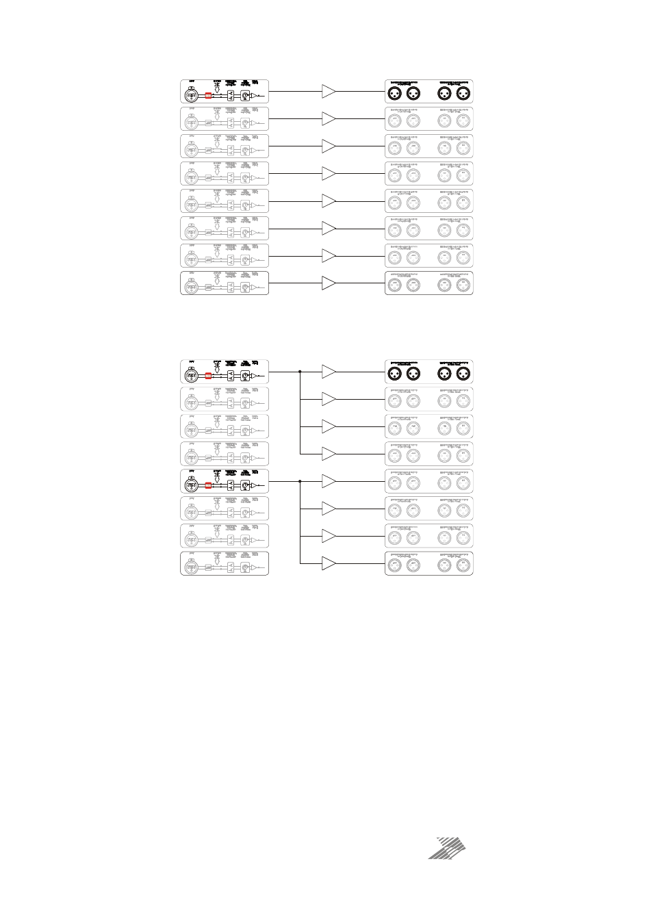
Input to output paths with “O/B Split” features disabled.
-10dB
-10dB
0dB
0dB
-10dB
-10dB
0dB
0dB
INPUT
CHANNEL 1
INPUT
CHANNEL 2
INPUT
CHANNEL 3
INPUT
CHANNEL 4
INPUT
CHANNEL 5
INPUT
CHANNEL 6
INPUT
CHANNEL 7
INPUT
CHANNEL 8
OUTPUT
CHANNELS 1
OUTPUT
CHANNELS 2
OUTPUT
CHANNELS 3
OUTPUT
CHANNELS 4
OUTPUT
CHANNELS 5
OUTPUT
CHANNELS 6
OUTPUT
CHANNELS 7
OUTPUT
CHANNELS 8
Input to output paths with “O/B Split” features enabled.
The FOH and MON output sockets also have sensing circuitry to detect the presence of 48V
phantom power being sent from a desk. This can then enable the local 48V power to be
switched onto the respective input on the unit.
These sense signals are logically controlled — each has a respective rear panel “safe” switch
that has to be
disabled
to allow the remote echoing of the sensed phantom power to operate
the local source in the unit.
There is also a “safe” switch” to disable the front panel 48V switching if required. This facility
does NOT disable the 48V LEDs on the front panel — these will still operate as a safety
measure to show which channels will have phantom power applied should the “safe” switch
be disabled.