Ta x, Internal block diagrams and description – XTA DS8000/D User Manual
Page 13
Page 13
DS8000 Operator’s Manual
ta
x
8: AES option: This DB25 socket (not fitted unless option is present) provides multiple AES
digital output feeds and may be used in conjunction with the word clock I/O BNC socket.
Please see the ADC option set-up, starting on page 18.
9: Pin 1 lift switches: To isolate the ground connections of either the FOH outputs or MON
outputs, each bank of eight can have their ground (earth) connection isolated from the local
ground within the unit.
10: FOH and MON outputs: The “Front of House” and “Monitor” sockets are electronically
balanced outputs with a maximum level of +20dB (into 600R) capable of driving long cables
with excellent CMR to minimise noise pick-up.
11: Sample rate LED: Tri-colour LED shows sample rate of AES outputs (if option fitted)
Please see the ADC option set-up, starting on page 18.
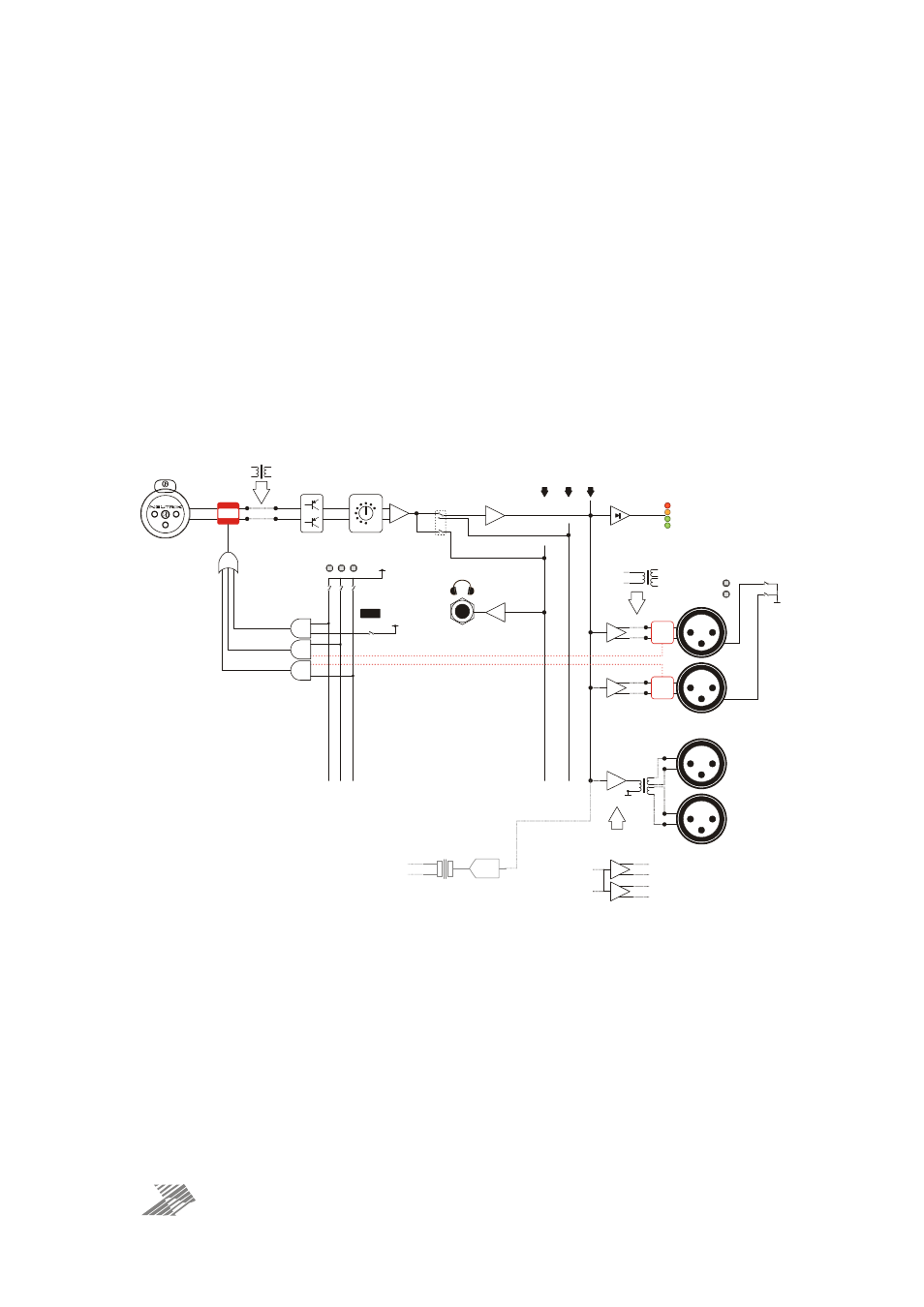
Internal Block Diagrams and Description
TX OPTION
DIFFERENTIAL
DISCRETE
MIC PRE-AMP
DIFF.
SWITCHED
GAIN STAGE
-6dB
+42
DE-BAL
STAGE
“O/B SPLIT”
BUS
“SOLO”
BUS
INV.
BUFFER
TX OPTION
PER PAIR
ELECTRONIC
OPTION
PER PAIR
+18dB
-20
“CHANNEL”
BUS
METER
RECTIFIER
METER
COMPARATORS
“SOLO”
SW ITCH
“O/B SPLIT”
SW ITCH
HEADPHONE
AMPLIFIER
(MONO)
48V
SENSE
48V
SENSE
+5V
“MON”
“FOH”
INPUT
+5V
48V “SAFE” SW ITCHES
(REAR PANEL)
F
R
O
N
T
P
A
N
E
L
C
O
N
T
R
O
L
S
E
N
S
E
“
M
O
N
”
C
O
N
T
R
O
L
S
E
N
S
E
“
F
O
H
”
C
O
N
T
R
O
L
+12
0
PIN 1 LIFT
SW ITCHES
(REAR PANEL)
L
IF
T
M
O
N
IT
O
R
P
IN
1
’S
L
IF
T
F
R
O
N
T
O
F
H
O
U
S
E
P
IN
1
’S
96K A-D
CONVERTER
OPTION
(PER PAIR OF INPUTS)
+48V
SW ITCHES
(FRONT PANEL
PER CHANNEL)
+48V
DB25
0dB
0dB
-10dB
-10dB
REAR PANEL
OUTPUTS
FRONT PANEL
OUTPUTS
One channel is shown above. The input signal is fed, still balanced, to a discrete transistor
pre-amplifier, which includes the gain switching control on the front panel. Following this,
the signal is debalanced and fed in parallel to a pair of CMOS soft switches. The front panel
“Solo” switch enables the addition of this channel’s signal to the solo bus (additive). The rear
panel “O/B Split” switch(s) toggle a changeover action between the signal going either
directly to an individual channel’s bus, or to the “O/B Split” bus which feeds the common bus
to a group of four output channels (with 1-4 or 5-8).
The output bus signal is split to individual output drivers in the case of the rear panel
electronically balanced outputs (FOH and MON) at 0dB, and a driver for the transformer
balanced outputs on the front panel. These outputs are two sets of taps from the same
transformer and operate at —10dB. The output bus signal also feeds a precision rectifier
stage to drive the channel metering.