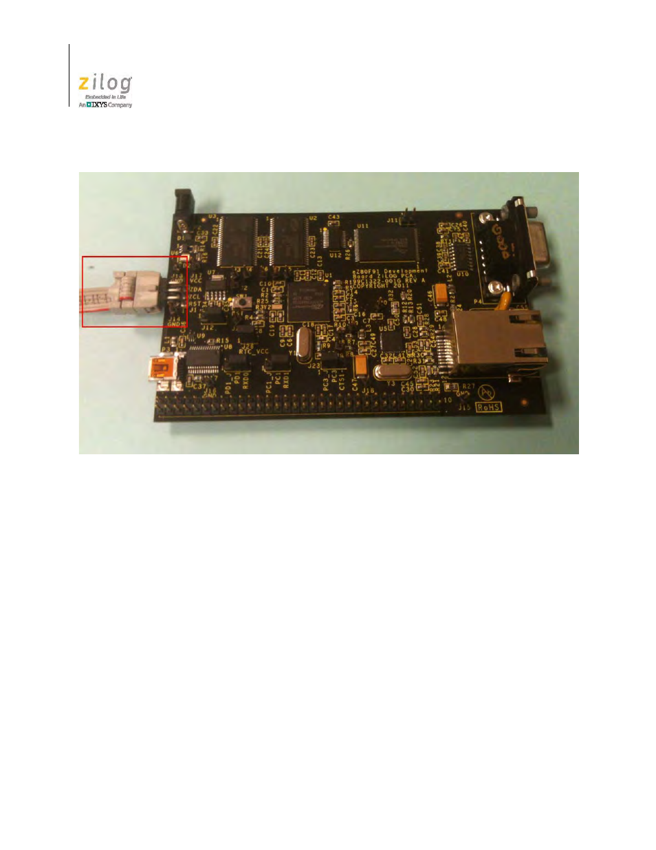
Figure 4, Debug connector j1 – Zilog EZ80F91GA User Manual
Page 22
Advertising
The ZGATE Embedded Security Development Kit
UM024502-1012
10
ZGATE Embedded Security Development Kit
User Manual
4. Connect an Ethernet CAT5 cable to P1 and to your Ethernet hub.
5. With the USB A (male) to Mini-B cable, connect Port P3 on the ZGATE Embedded
Security Development Board to a USB port on the development PC to apply power to
the Development Board, as highlighted in Figure 5.
Figure 4. Debug Connector J1
Advertising
See also other documents in the category Zilog Sensors:
- S3F94C8 (11 pages)
- S3F80QB (29 pages)
- S3F8S19 (38 pages)
- Z51F6412 (55 pages)
- Z51F6412 (96 pages)
- Z51F6412 (54 pages)
- EZ80F93 (11 pages)
- Z16F6411 (20 pages)
- Z16F6411 (216 pages)
- EZ80F93 (13 pages)
- ZMOT0BSB (314 pages)
- ZMOT0BSB (582 pages)
- Z8F083A (14 pages)
- Z8F2480 (17 pages)
- Z8F082A (18 pages)
- Z8F082A (15 pages)
- Z8F0822 (17 pages)
- Z8F6423 (83 pages)
- Z8F2480 (19 pages)
- Z8F2480 (18 pages)
- Z8F6423 (18 pages)
- Z8F6423 (27 pages)
- Z8F6482 (50 pages)
- EZ80F915 (411 pages)
- EZ80F91NAA (34 pages)
- EZ80F91 (41 pages)
- EZ80L92 (40 pages)
- EZ80L92 (26 pages)
- EZ80L92 (79 pages)
- EZ80F91GA (469 pages)
- EZ80L92 (10 pages)
- eZ80F92 (87 pages)
- Z16FMC6 (520 pages)
- Z8FMC16 (26 pages)
- Z16FMC6 (41 pages)
- ZUSBOPTS (38 pages)
- ZUSBOPTS (59 pages)
- Z16FMC6 (26 pages)
- Z16FMC6 (8 pages)
- ZMOT1AHH (25 pages)
- ZMOT0BSB (34 pages)
- EZ80F915 (78 pages)
- EZ80190 (87 pages)
- EZ80L92 (86 pages)