Rear panel connectors and outputs – AMETEK HPD Series Operation Manual User Manual
Page 15
Advertising
Section 1. Features and Specifications
Rear Panel Connectors and Outputs
Figure 1.2
shows the programming interface indicators for units that have a digital
programming interface installed.
Figure 1.2 Remote Programming Interface Indicators
Rear Panel Connectors and Outputs
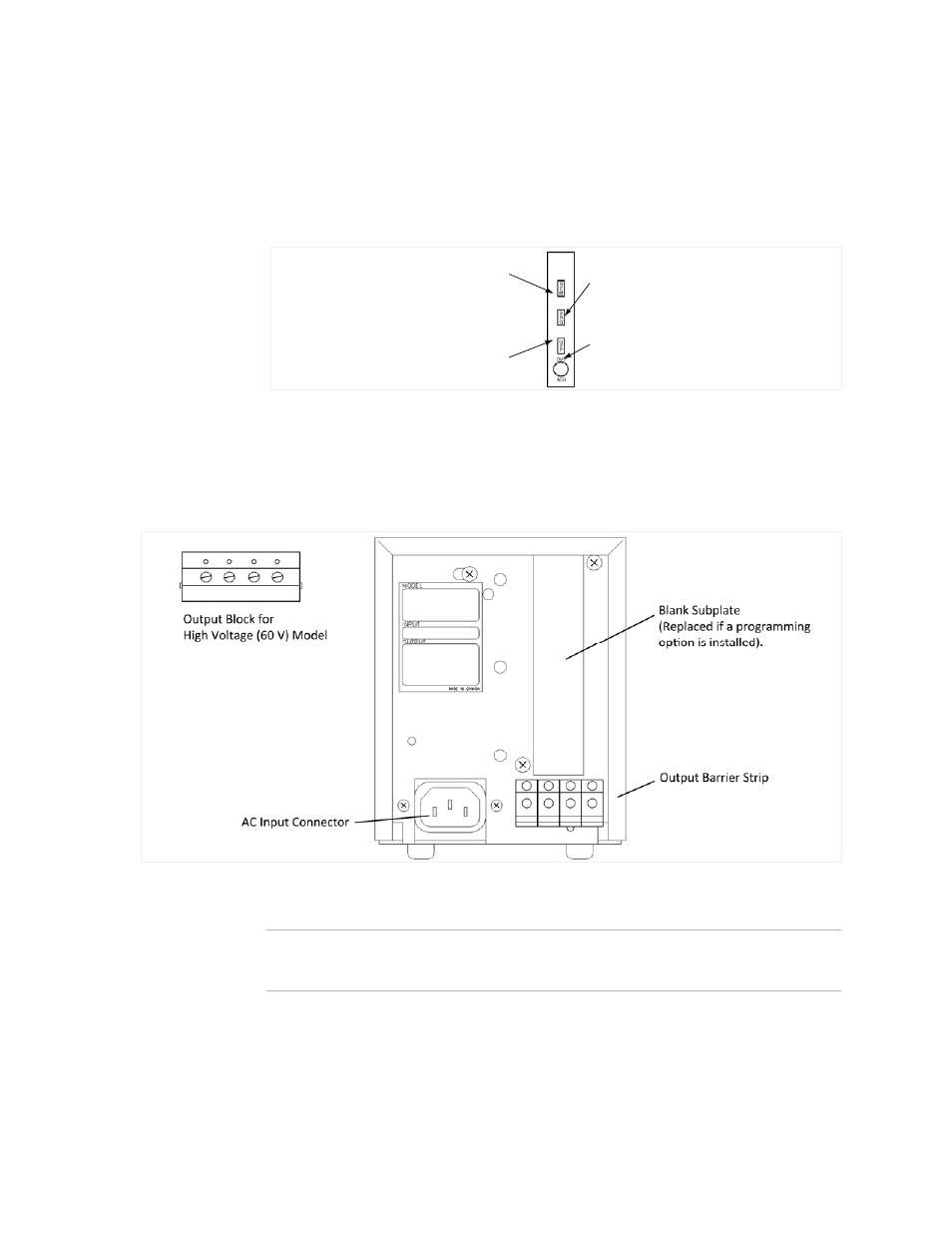
Figure 1.3
shows the connectors and outputs available at the rear panel. (
Figure 1.3
shows the 15 V or 30 V low voltage model.)
Figure 1.3 Rear Panel
Note
The power supply is shipped with jumpers for local sensing of the output voltage. See
“Local Sensing” on page 17
.
3
Remote Programming LED (REM)
Shutdown LED (SRQ)
OVP Adjust Potentiometer (OVP ADJ)
OVP Shutdown (OVP)
Advertising