AMETEK XBT Series Installation User Manual
Xbt rackmount installation
Technical Note
XBT Rackmount Installation
Document No. M370187-05 Rev A • 7/3/2008
PURPOSE
Provide instructions for assembling XBT rackmount kits.
PARTS
•
rackmount piece
•
filler panel
•
M3.0 (3mm) screws (2 per benchtop unit; 3 per filler panel)
•
M5.0 (5mm) screws (4 per rackmount)
TOOLS
Philips head screwdriver (not supplied with kit)
SUMMARY OF PROCEDURES
Remove feet from benchtop unit; attach rackmount parts (rackmount piece and filler panel if installing single unit), and insert and
secure to rack. See Figure 10 and Figure 11, for dimensions drawings in last section of this document.
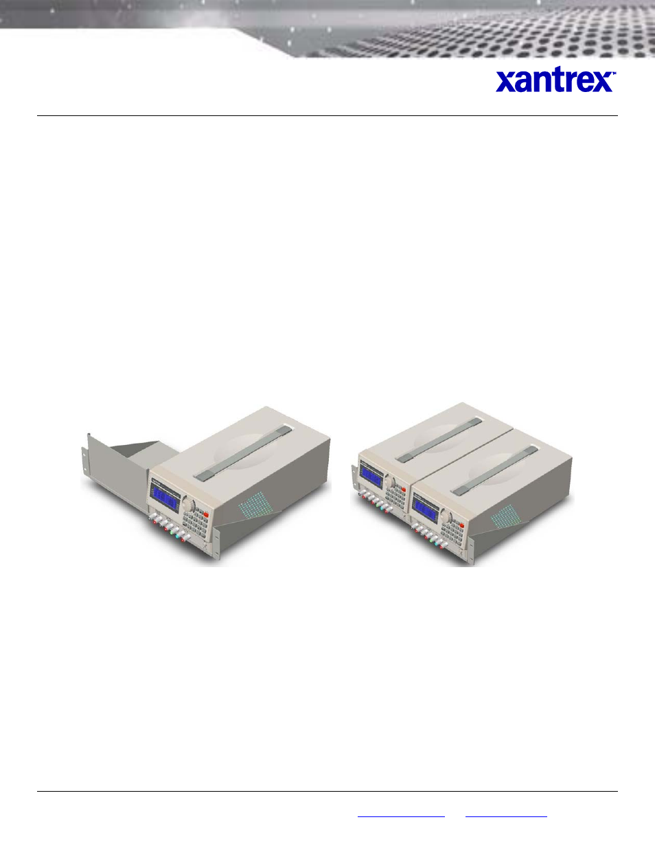
Assembled Rackmounts: Single (Figure 1) and Duo (Figure 2).
Figure 1. Rackmount with Single Unit and Filler Panel
Figure 2. Rackmount with Two Units
PROCEDURES
1. On an appropriate work surface (flat and sturdy), place unit with bottom face up.
2. Remove rubber pads from each of four feet.
3.
Unscrew
and remove four feet. (Recommend keeping together rubber pads, screws and feet in event that
unit is ever needed for benchtop use).
4. With unit still in bottom-up position, lay rackmount piece on unit with its front lip overhanging front of unit and
one side (right or left) flush against same (corresponding) side of unit, and with screw holes on rackmount
piece aligned with holes where feet were removed from unit (
Figure 3
).
©2008 Programmable Division of Xantrex Technology Inc. • All rights reserved. • Xantrex is a trademark of Xantrex International, registered in the U.S. and other countries.
9250 Brown Deer Road, San Diego CA 92121 • Tel: 858-450-0085 • Fax: 858-458-0267 • email:
• Web:
www.programmablepower.com
1 of 6