Aplex Technology ARCHMI-912 User Manual
Page 34
ARCHMI-9XX Series User Manual
33
22. LED1:
LED1: LED STATUS. Green LED for Touch Power status.
23. JP1:
(2.0mm Pitch 2x3 Pin Header), COM1 jumper setting, pin 1~6 are used to select
signal out of pin 9 of COM1 port.
JP1 Pin#
Function
Close 1-2
COM1 RI (Ring Indicator) (default)
Close 3-4
COM1 Pin9: DC+5V (option)
Close 5-6
COM1 Pin9: DC+12V (option)
24. S_232
(Switch), COM1 jumper setting, it provides selectable RS232 or RS422 or RS485
serial signal output.
Function
S_232 Pin#
RS232 (Default)
ON: Pin1, Pin2, Pin3, Pin4
RS422 (option)
OFF: Pin1, Pin2, Pin3, Pin4
RS485 (option)
OFF: Pin1, Pin2, Pin3, Pin4
25. S_422:
(Switch), COM1 setting, it provides selectable RS232 or RS422 or RS485 serial
signal output.
Function
S_422 Pin#
RS232 (Default)
OFF: Pin1, Pin2, Pin3, Pin4, Pin5
RS422 (option)
ON: Pin1, Pin2, Pin3, Pin4, Pin5
RS485 (option)
ON: Pin1, Pin2, Pin3, Pin4, Pin5
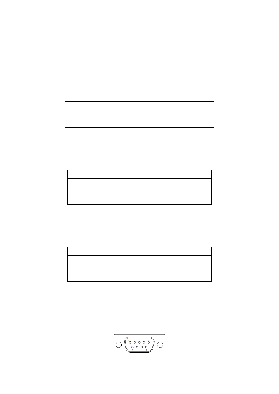
26. COM1
(Type DB9M), Rear serial port, standard DB9 Male serial port is provided to
make a direct connection to serial devices. COM1 port is controlled by pins No.
1~6 of JP1, select output Signal RI or 5V or 12V, For details, please refer to
description of JP1 and S_232 and S_422 setting.