2 on-board leds, 3 comx ab-cd connectors, 2 on-board leds 3.1.3 comx ab-cd connectors – Artesyn COMX-P40x0 ENP2 Installation and Use (January 2015) User Manual
Page 47: Table 3-3, Module led status, Table 3-4, Comx ab-cd connectors, Controls, leds, and connectors
Advertising
Controls, LEDs, and Connectors
COMX-P40x0 ENP2 Installation and Use (6806800R95C)
47
3.1.2
ON-BOARD LEDS
There are several status LEDs provided on the module. The following table lists the LED
functions.
3.1.3
COMX AB-CD Connectors
The following table lists the pinout of the AB- CD COMX connectors for the P40x0 COMX
modules:
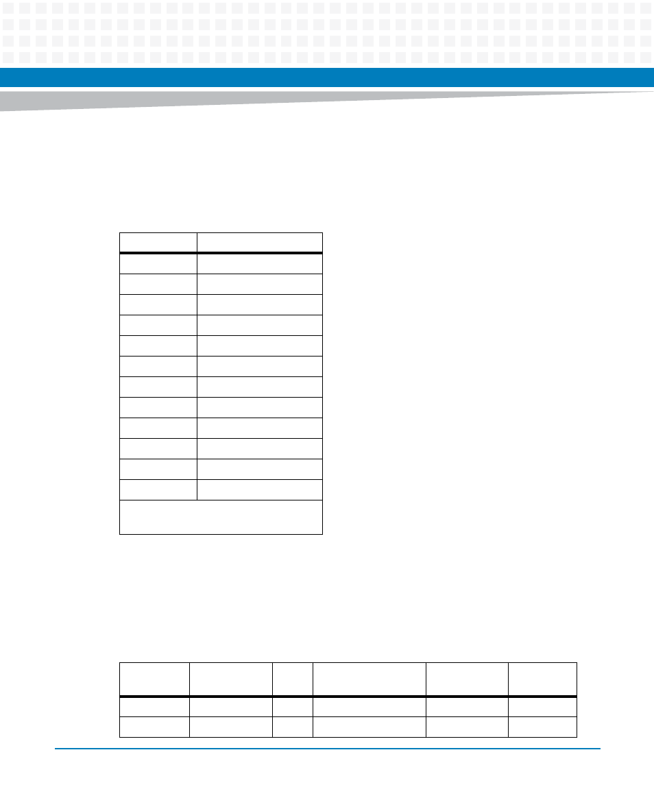
Table 3-3 Module LED Status
LED
Status
D17
Thermal issue
D18~D19
Debug LED 1~2
D3
System asleep
D7
DDR3 power OK
D4
3.3 V power OK
D5
2.5 V power OK
D6
1.8 V power OK
D13
CORE power OK
D9
PLATFORM power OK
D10
1.5 V power OK
D15
USB hub 2 active
D16
USB hub 2 high speed
D1, D2, D15, D16 are for modules with
USB port options.
Table 3-4 COMX AB-CD Connectors
Connector
ref
Connector
name
Pin
Net Name
Direction from
COMX
Notes
J2
AB1
A1
GND
J2
AB1
A2
LAN1_MDI_N<3>
bidir
Advertising