2 processor cop header (j25), Table 5-18, Processor cop header (j25) pin assignments – Artesyn MVME3100 Single Board Computer Installation and Use (June 2014) User Manual
Page 104: Processor cop header (j25), Pin assignments
Pin Assignments
MVME3100 Single Board Computer Installation and Use (6806800M28E)
104
Pin 12 must be grounded in the cable in order to enable boundary scan.
5.3.2
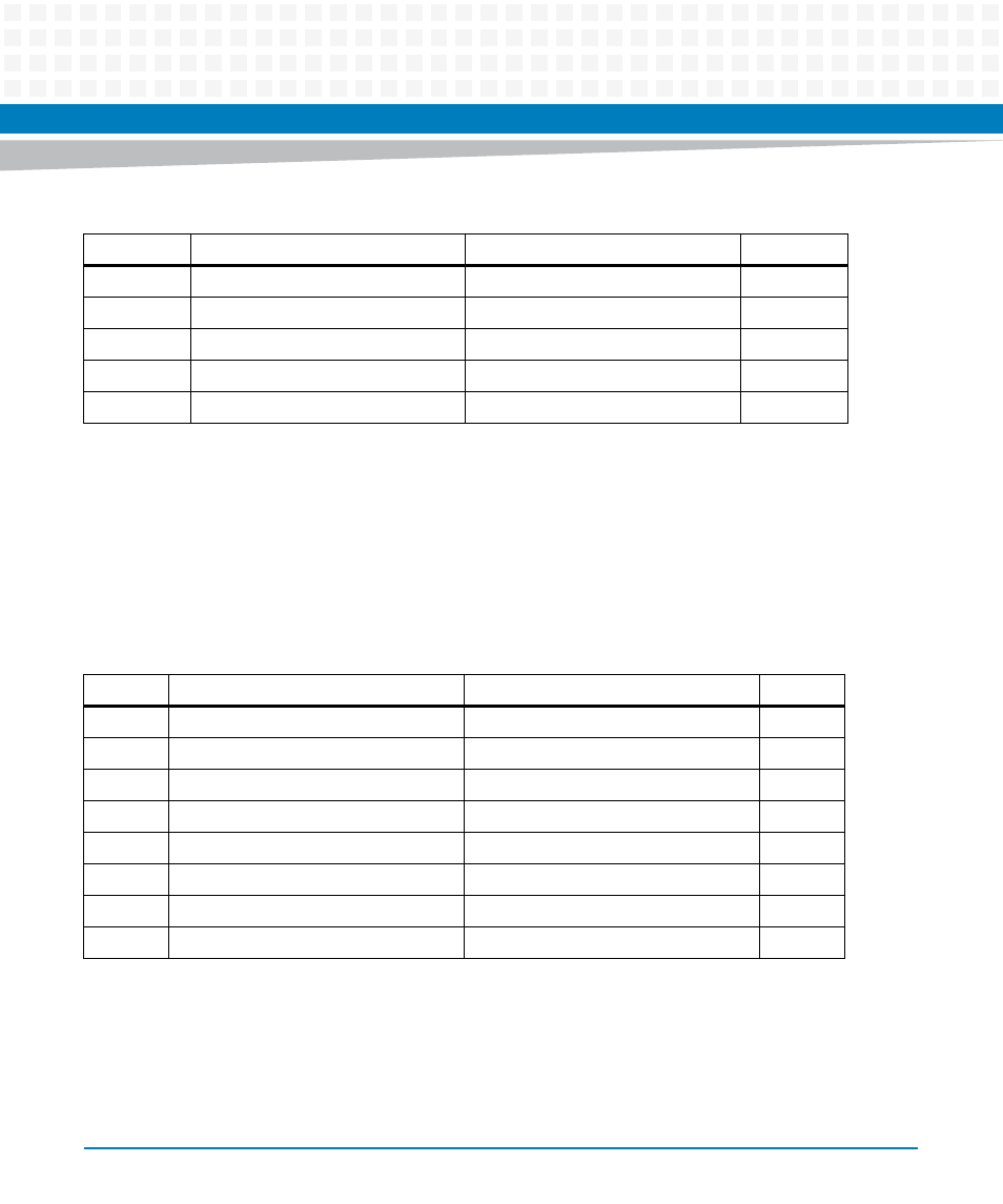
Processor COP Header (J25)
There is one standard 16-pin header that provides access to the COP function. The pin
assignments for this header are as follows:
Pin 6 +3.3V has a resettable fuse and can supply up to 0.5A to power I/O buffers in the COP
controller.
5
TDI
GND 6
7
TMS
GND 8
9
TCK
GND 10
11
NC
GND (BSCANEN_L)
12
13
BSCAN_AW_L
GND
14
Table 5-17 Boundary Scan Header (J24) Pin Assignments (continued)
Pin
Signal
Signal
Pin
Table 5-18 Processor COP Header (J25) Pin Assignments
Pin
Signal
Signal
Pin
1
CPU_TDO
No Connect
2
3
CPU_TDI
CPU_TRST_L
4
5
Pullup
CPU_VIO (+3.3V)
6
7
CPU_TCK
CPU_CKSTPI_L
8
9
CPU_TMS
No Connect
10
11
CPU_SRST_L
GND (optional pull-down)
12
13
CPU_HRST_L
KEY (no pin)
14
15
CPU_CKSTPO_L
GND
16