Functional description – Artesyn MVME3100 Single Board Computer Installation and Use (June 2014) User Manual
Page 70
Functional Description
MVME3100 Single Board Computer Installation and Use (6806800M28E)
70
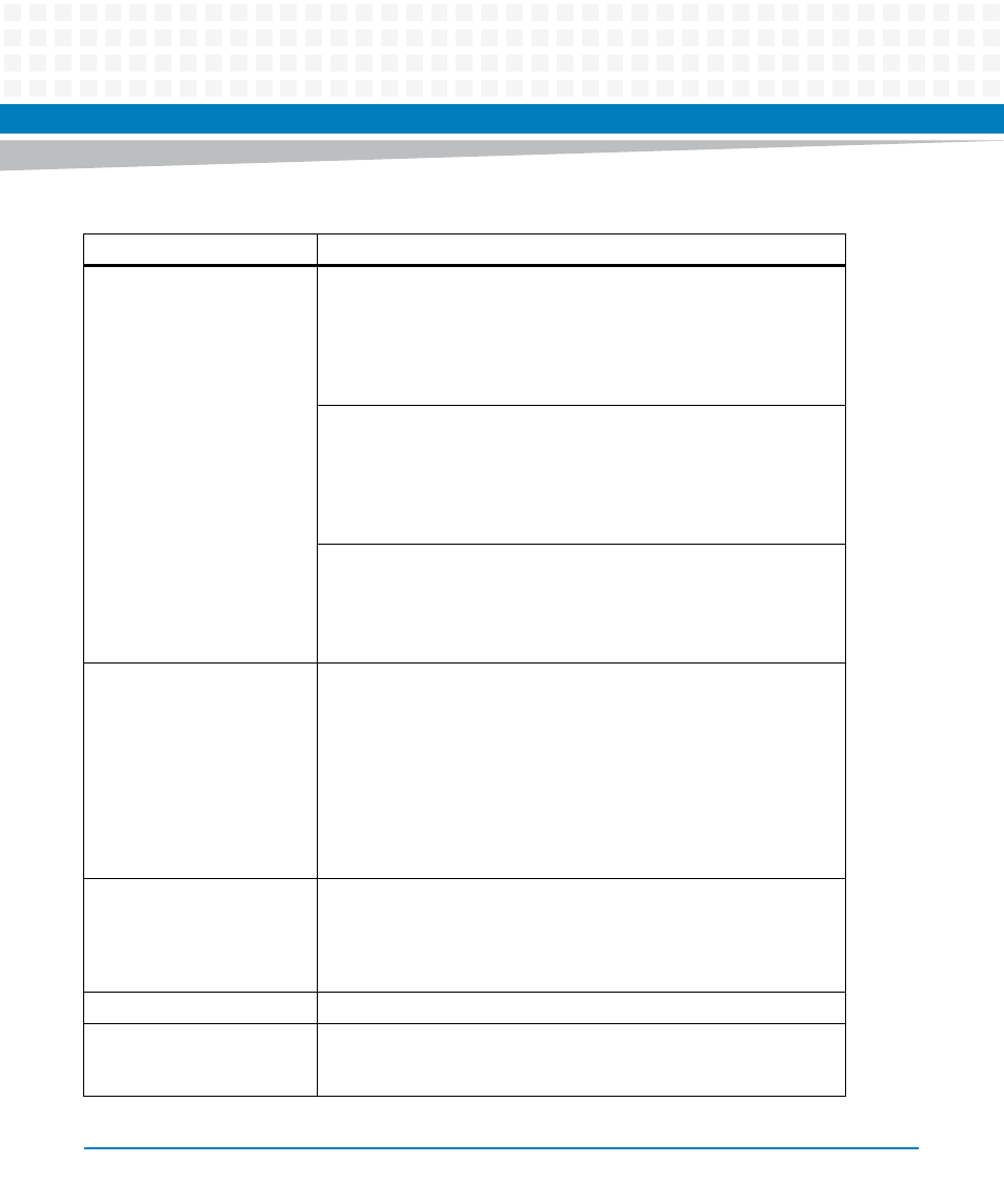
PCI Interface
Bus A:
– 66 MHz PCI-X mode
– One TSi148 VMEbus controller
– One serial ATA (sATA) controller
– One MPC8540
– Two PCI6520 PCI-X-to-PCI-X bridges (primary side)
Bus B:
– 33/66/100 MHz PCI/PCI-X (PCI 2.2 and PCI-X 1.0b compliant)
– Two +3.3V/5V selectable VIO, 64-bit, single-wide PMC sites or one
double-wide PMC site (PrPMC ANSI/VITA 32-2003 and PCI-X Auxiliary
ANSI/VITA 39-2003 compliant)
– One PCI6520 PCI-X-to-PCI-X bridge (secondary side)
Bus C (-1263 version):
– 33 MHz PCI (PCI 2.2 compliant)
– One USB 2.0 controller
– One PCI expansion connector for interface to PMCspan
– One PCI6520 PCI-X-to-PCI-X bridge (secondary side)
I/O
– One front panel RJ45 connector with integrated LEDs for front I/O: one
serial channel
– One front panel RJ45 connector with integrated LEDs for front I/O: one
10/100/1000 Ethernet channel
– One front panel external sATA data connector for front I/O: one sATA
channel
– One front panel USB Type A upright receptacle for front I/O: one USB
2.0 channel (-1263 version)
– PMC site 1 front I/O and rear P2 I/O
– PMC site 2 front I/O
Serial ATA
– One four-channel sATA controller: one channel for front-panel I/O, one
channel for planar I/O, one channel for future rear P0 I/O, and one
channel is not used
– One planar data connector and one planar power connector for an
interface to the sATA hard disk drive
USB (-1263 version)
– One four-channel USB 2.0 controller: one channel for front panel
Ethernet
– Two 10/100/1000 MPC8540 Ethernet channels for front-panel I/O and
rear P2 I/O
– One 10/100 MPC8540 Ethernet channel for rear P2 I/O
Table 4-1 MVME3100 Features Summary (continued)
Feature
Description