4 local bus controller chip select assignments, Table 7-3, Lbc chip select assignments – Artesyn MVME3100 Single Board Computer Installation and Use (June 2014) User Manual
Page 130: Local bus controller chip select assignments, Programming details
Programming Details
MVME3100 Single Board Computer Installation and Use (6806800M28E)
130
Refer to the MPC8540 Reference Manual listed in
Appendix B, Related Documentation
, for
additional details regarding the operation of the MPC8540 PIC.
7.4
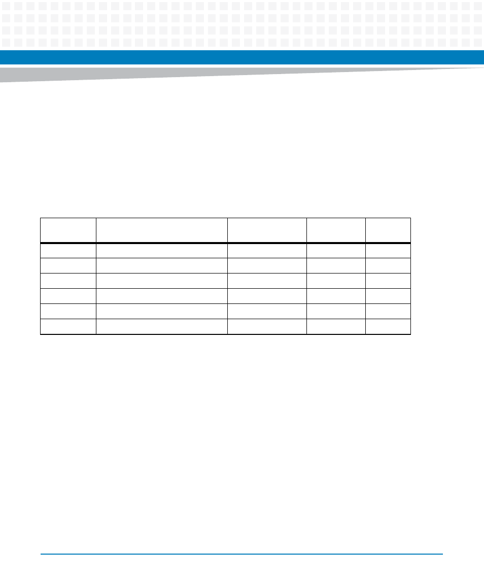
Local Bus Controller Chip Select Assignments
The following table shows local bus controller (LBC) bank and chip select assignments for the
MVME3100 board.
Table 7-3 LBC Chip Select Assignments
LBC Bank/
Chip Select
Local Bus Function
Size
Data Bus
Width
Notes
0
Boot Flash bank
32MB - 128MB
32 bits
1
1
Optional second Flash bank
32MB - 128MB
32 bits
1
2
Control/Status registers
64 KB
32 bits
2
3
Quad UART
64 KB
8 bits
4
32-bit timers
64 KB
32 bits
3
5-7
Not used
1. Flash bank size determined by VPD flash packet.
2. Contro/Status registers are byte read and write capable.
3. 32-bit timer registers are byte readable, but must be written as 32 bits.