7 five-row p2 adapter (mvme761-011), 8 connectors and cables, Figure 1-3 – Artesyn MVME7616E Transition Module Installation and Use (April 2015) User Manual
Page 17: Five row p2 adapter, General information
General Information
MVME7616E Transition Module Installation and Use (6806800A43D)
17
1.7
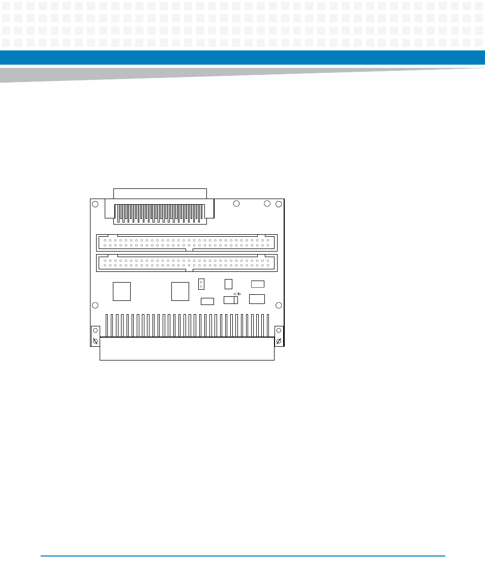
Five-Row P2 Adapter (MVME761-011)
The P2 adapter for the MVME761-011 mounts onto a 5-row, 160-pin P2 backplane connector.
The 68- pin female connector, J1, carries 16-bit SCSI signals from the host VMEmodules. It also
has a 64-pin male connector, J3, for PMC I/O.
This P2 adapter, and the cable for connecting to the MVME761 transition module, can be
ordered separately as model MVME761P2-011.
1.8
Connectors and Cables
The connectors on the MVME761 transition module and the P2 adapters are listed in the
following tables. The port connectors are located on the front panel, which is shown in
Chapter 4, Connector Pin Assignments
.
The cable used for connecting the MVME761 transition module to the P2 adapter is provided
with the MVME761-0x1
Figure 1-3
Five Row P2 Adapter
J5
2
1
1
64
63
+
U1
9
25
17
CR1
R4
C8
C9
U3
P1
1
32
2
1
64
63
J1
J3
J4
1
U2
9
25
17
+
1
33
D
C
B
A
Z
D
C
B
A
Z