Procedure, Figure 2-2, Sim configuration – Artesyn MVME7616E Transition Module Installation and Use (April 2015) User Manual
Page 22: Hardware preparation and installation
Hardware Preparation and Installation
MVME7616E Transition Module Installation and Use (6806800A43D)
22
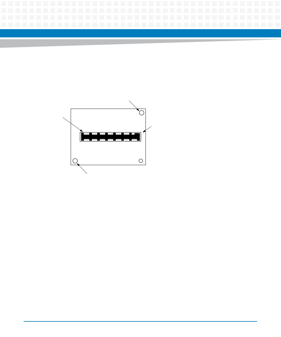
You must set the jumpers and install the SIMs prior to installing the MVME761 transition
module in the system chassis.The SIMs plug into connector J1 (for serial port 3) or J12 (for serial
port 4) on the MVME761 transition module.
Procedure
Install the SIMs on the MVME761 transition module per the following procedure:
1. Align the SIM so that P1 on the SIM lines up with the appropriate SIM connector (J1
for serial port 3 or J12 for serial port 4) on the transition module. Note the position
of the alignment key on P1. See
.
2. Place the SIM onto the transition module SIM connector, making sure that the
mounting holes also line up with the standoffs on the transition module as shown
in
.
3. Gently press the top of the SIM to seat it on the transition module SIM connector. If
the SIM does not seat with gentle pressure, re-check the alignment of the
connectors.
Figure 2-2
SIM Configuration
Mounting Hole
Mounting Hole
Alignment
P1
Key
11637 9610