Connector pin assignments, 1 overview, 2 p2 connector – Artesyn MVME7616E Transition Module Installation and Use (April 2015) User Manual
Page 41: 1 overview 4.2 p2 connector, Table 4-1, P2 connector pin assignments, S. see, Chapter 4, connector pin assignments, Chapter 4
Chapter 4
MVME7616E Transition Module Installation and Use (6806800A43D)
41
Connector Pin Assignments
4.1
Overview
This chapter provides the pin assignments for the P2 connector and front panel port
connectors on the MVME761 transition module, as well as for the SCSI and PMC I/O connectors
on the P2 adapters.
4.2
P2 Connector
Signaling and power from the host VMEmodules are received through connector P2, a 64-pin
DIN connector. Because the P2 adapter reroutes some of the signals, connector P2 on the
MVME761 transition module is not pin-for-pin compatible with connector P2 on the host
VMEmodules.
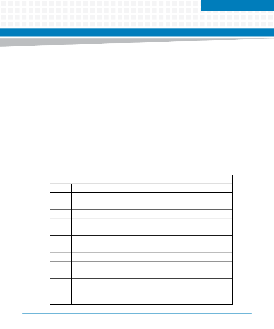
The pin assignments and signal mnemonics for the MVME761 transition module P2 connector
are listed in the following table.
Table 4-1 P2 Connector Pin Assignments
Row A Pins
Row C Pins
Pin
Signal
Pin
Signal
1
C- (R- for RJ-45 J9)
1
C+ (R+ for RJ-45 J9)
2
T-
2
T+
3
R-
3
R+
4
+12VF
4
PRSTB#
5
GND
5
PRD0
6
PRD1
6
PRD2
7
PRD3
7
PRD4
8
PRD5
8
PRD6
9
PRD7
9
GND
10
PRACK#
10
GND
11
PRBSY
11
PRPE
12
PRSEL
12
INPRIME#
13
PRFAULT#
13
GND