2 rtm connectors, Table 3-3, Rtm rp0 connector pin assignment – Artesyn MVME8100 RTM (VXS1-RTM1) Installation and Use (April 2015) User Manual
Page 34: Controls, leds, and connectors, 1 vme/vxs rp0 connector
Controls, LEDs, and Connectors
VXS1-RTM1 Installation and Use (6806800P46C)
34
3.1.2.2
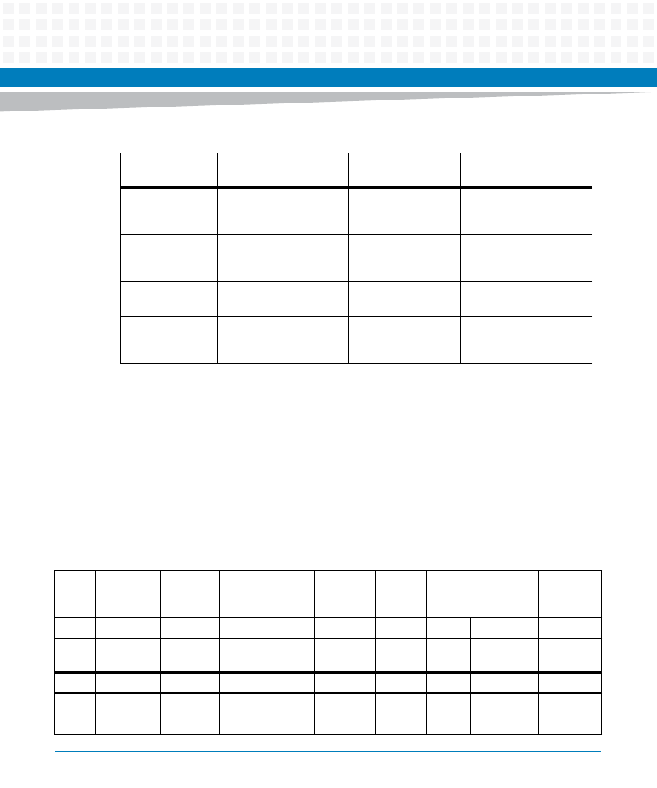
RTM Connectors
The following sections describe the pin out of headers and connectors used on the RTM.
3.1.2.2.1 VME/VXS RP0 Connector
This high speed connector is defined by VITA41.7 standard. This connector is used to connect
high speed signals such as USB3.0, DisplayPort, SATA etc.
The pin assignment is shown in the table below:
J5
Dual Ethernet
Dual Ethernet RJ45 with
magnetics connector on
front panel
J6
eSATA
Dual stacked eSATA Port
1 and 2 connector on
front panel
J10, J14
PIM I/O
I/O connector for PMC
rear signals
S1
DIP Switch
Six position switch for
EEPROM address
selection
Table 3-2 RTM Connectors (continued)
Reference
Designator
Function
Pinout Definition
Description
Table 3-3 RTM RP0 Connector Pin Assignment
RTM
Board
RP0
Row G
Row F
Row E
Row D
Row C
Row B
Row A
Even
Odd
Even
Odd
Bplan
e RJ0
Row I
Row H
Row G
Row F
Row E
Row D
Row C Row B
Row A
1
VOID GND GND
VOID
VOID GND
GND
VOID VOID
2
VOID VOID
VOID
VOID
VOID VOID
VOID
VOID VOID
3
VOID VOID
VOID
VOID
VOID VOID
VOID
VOID VOID