4 alarm connector, Table 3-2, Alarm pin description – Artesyn SAM1411 Installation and Use (September 2014) User Manual
Page 39: Figure 3-2, Alarm i/o connector pinout, Controls, indicators, and connectors
Controls, Indicators, and Connectors
SAM1411 Installation and Use (6806800M91B)
39
3.4
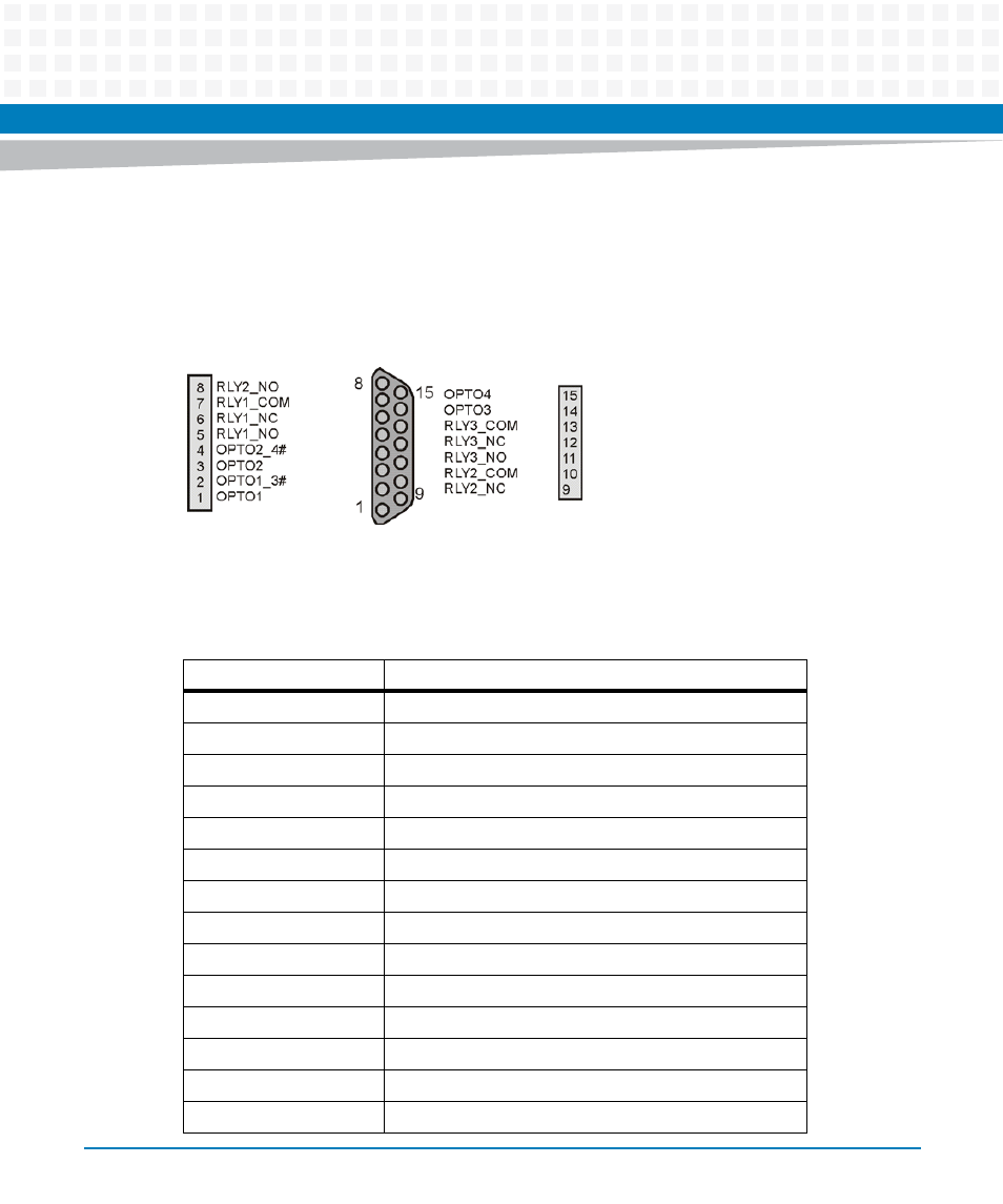
Alarm Connector
The DB15 connector provides a means to report system alarm conditions to a higher level such
as a system operator console.
displays the pinout for the alarm I/O connector:
The following table shows the description of the pins:
Figure 3-2
Alarm I/O Connector Pinout
Table 3-2 Alarm Pin Description
Pin
Description
1
Minor Alarm Reset +
2
Minor Alarm Reset -
3
Major Alarm Reset +
4
Major Alarm Reset -
5
Critical Alarm - NO (Normally Open)
6
Critical Alarm - NC (Normally Closed)
7
Critical Alarm - COM (Common)
8
Minor Alarm - NO (Normally Open)
9
Minor Alarm - NC (Normally Closed)
10
Minor Alarm - COM (Common)
11
Major Alarm - NO (Normally Open)
12
Major Alarm - NC (Normally Closed)
13
Major Alarm - COM (Common)
14
Pwr Alarm - NO (Normally Open)