Controls and indicators, Installation – Basler Electric CBS 212A User Manual
Page 11
9270700990 Rev F
5
Controls and Indicators
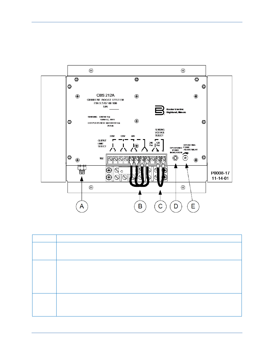
CBS 212A controls and indicators consist of screwdriver-adjusted controls, jumper wires, and an indicator
light. See Figure 2. The call-outs (A, B, C, D, and E) of Figure 2 are listed in Table X along with a
description of each component.
Figure 2. Controls and Indicators
Table 1. Component Descriptions
Call-Out
Description
A
Output Limit Adjustment. This screwdriver-adjusted control is used to set the output
voltage limit of the CBS 212A. The adjustment range is 50 to 100 percent of the selected
output limit.
B
Output Limit Select. The output limit is selected by positioning this pair of jumper wires at
the appropriate terminals. Nominal output limits of 60, 120, or 220 Vdc can be selected by
repositioning the jumper wires. Jumper wire connections at TB2-1 and 2 select a 220 volt
output limit, connections at TB2-3 and 4 select a 120 volt limit, and connections at TB2-5
and 6 select a 60 volt limit. The other ends of the jumper wires must always be connected
to terminals TB2-7 and 8.
C
Sensing Voltage Select. The nominal sensing voltage is selected by positioning this jumper
wire. Nominal sensing voltage levels of 120 Vac or 240 Vac can be selected. Jumper wire
connections at terminals TB2-9 and 11 select 240 Vac sensing voltage. Jumper wire
connections at terminals TB2-10 and 11 select 120 Vac sensing voltage.
CBS 212A
Controls and Indicators