Interconnection, Ct connections, Current boost module connections – Basler Electric CBS 212A User Manual
Page 17
9270700990 Rev F
11
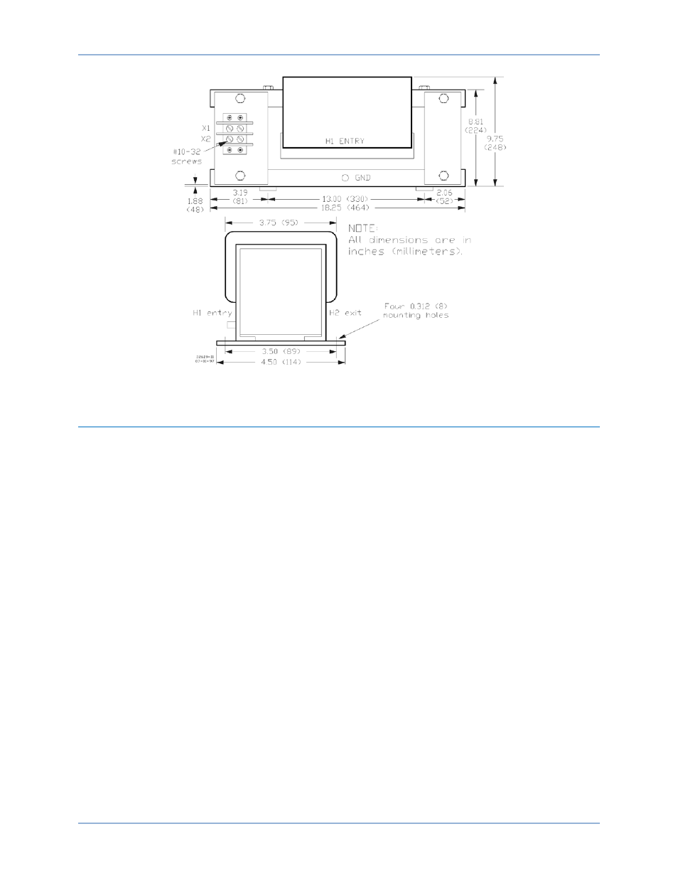
Figure 9. BE25930001 CT Dimensions
Interconnection
Typical CBS 212A connections are shown in Figure 10.
CT Connections
When the CTs are connected as shown in CBS 212A, energy is supplied to the Current Boost Module
during the following fault conditions.
a.
Symmetrical, three-phase short-circuit (A-phase to B-phase to C-phase)
b.
A-phase to B-phase short-circuit
c.
A-phase to C-phase short-circuit
d.
B-phase to C-phase short-circuit
e.
A-phase to Neutral short-circuit
f.
B-phase to Neutral short-circuit
If the generator has a Neutral terminal, energy will be supplied to the CTs during conditions e and f.
During a C-phase to Neutral short-circuit, energy will not be supplied to the CTs. In this case, if the
voltage regulator is powered by phase A and phase B, the regulator may continue to supply power to the
exciter field.
Current Boost Module Connections
Current Boost Module connections are shown in CBS 212A. The Sensing Voltage Select jumper and the
Output Limit Select jumpers must be properly configured for your application. Information about
positioning these jumpers is provided in the following paragraphs of the Calibration sub-section.
CBS 212A
Installation