Functional description, Introduction, Current boost module – Basler Electric CBS 212A User Manual
Page 9: Controls and indicators
9270700990 Rev F
3
Functional Description
Introduction
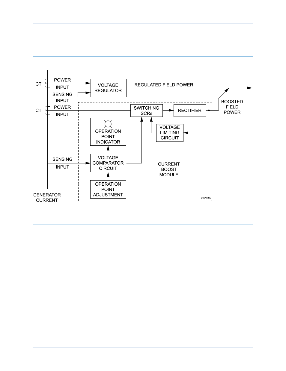
CBS 212Afunctions are illustrated in Figure 1 and described in the following paragraphs.
Figure 1. Function Block Diagram
Current Boost Module
The Current Boost Module rectifies the ac current received from the CTs and provides dc current boost to
the generator exciter field.
During normal generator operation, power from the generator output provides sufficient exciter field power
and the CBS 212A remains dormant. During normal operation, the CTs are effectively shorted by the
internal SCRs of the CBS 212A. Normal generator operation is indicated by the Operating Point Indication
LED being lit.
If the generator output voltage decreases below the operating-point setting, the CBS 212A detects the
voltage drop, turns off the Operating Point Indication LED, and removes the SCR “short-circuit” from the
CTs. The CBS 212A then provides full current boost to the generator exciter until the voltage returns to a
level just above the operating point setting. The Controls and Indicators and Installation chapters provide
information about setting the Operating Point Adjustment.
An adjustable voltage limiting circuit prevents the Current Boost Module output from exceeding the
specified percentage of the nominal output voltage (60, 120, or 220 Vdc). The Output Limit Select
Jumpers are used to select the nominal output voltage (60, 120, or 220 Vdc) and the Output Limit
Adjustment is used to set the desired percentage of the nominal output voltage. The Output Limit
Adjustment is adjustable over a range of 50 to 100 percent of the jumper-selected nominal output voltage.
CBS 212A
Functional Description