The interfaces, Power supply, Power supply to the power contacts – BECKHOFF BK7000 User Manual
Page 7: Power contacts, Fieldbus connection
Basic information
BK 7000
6
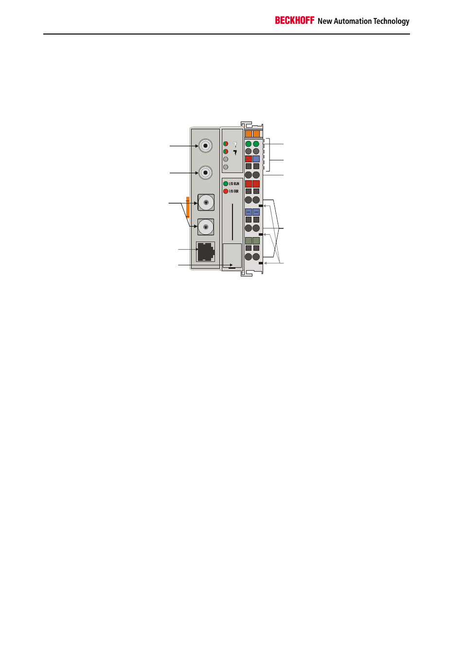
The interfaces
There are six ways of making a connection to a ControlNet bus coupler.
These interfaces are designed as plug connections and spring terminals.
The
ControlNet
coupler
BK7000
Power LEDs
Bus coupler / power contacts
Terminal bus
Power supply bus coupler
24 V DC / GND
Input
power contacts
power contacts
+ +
00
X0
PE PE
B
E
C
K
H
O
F
F
24V
0V
BK
70
00
ControlNet
Configuration
Interface
Network Access
Port (NAP)
Field Bus
Connector B
Field Bus
Connector A
0
9
8
7
6
5
4
3
2
1
0
9
8
7
6
5
4
3
2
1
Address
Selector
x10
x1
A
B
Power supply
24 V DC on the topmost
terminals
The bus couplers need an operating power of 24 V DC which is connected
via the topmost spring terminals, labeled "24 V” and "0 V”. This power sup-
ply serves not only the electronic components of the bus coupler but (via
the K bus) also the bus terminals. The power supply of the bus coupler
circuitry and that of the K-bus (Terminal bus) are electrically isolated from
the voltage of the field level.
Power supply to the power contacts
Lower 3 terminal pairs for
power input
maximum 24 V
maximum 10 A
The six lower connections with spring terminals can be used to supply
power to the peripherals. The spring terminals are connected in pairs to the
power contacts. The power supply to the power contacts has no connec-
tion to the power supply of the bus couplers. The power input is designed
to permit voltages up to 24 V. The pair-wise arrangement and the electrical
connection between the feed terminal contacts makes it possible to loop
through the wires connecting to different terminal points. The load on the
power contact may not continuously exceed 10 A. The current capacity
between two spring terminals is the same as the capacity of the connecting
wires.
Power contacts
Spring contacts at the side
On the right-hand side face of the bus coupler are three spring contacts
which are the power connections. The spring contacts are recessed in slots
to prevent them from being touched. When a bus terminal is connected,
the blade contacts on the left-hand side of the bus terminal are connected
to the spring contacts. The slot and key guides at the top and bottom of the
bus couplers and bus terminals ensure reliable location of the power con-
tacts.
Fieldbus connection
Control-Net connectors
On the left-hand side there are two ControlNet connectors A and B and a
NAP-Port. You will find a detailed description of the fieldbus interfaces in
another part of this manual (In the chapter "The transfer medium: plugs
and cables”).