Terminal configuration – BECKHOFF KL3201 User Manual
Page 11
Terminal configuration
KL3201, KL3202 and KL3204
9
Terminal configuration
The terminal can be configured and parameterized via the internal register
structure. Each terminal channel is mapped in the Bus Coupler. Depending
on the type of the Bus Coupler and the mapping configuration (e.g.
Motorola/Intel format, word alignment etc.) the terminal data are mapped in
different ways to the Bus Coupler memory. For parameterizing a terminal,
the control and status byte also has to be mapped.
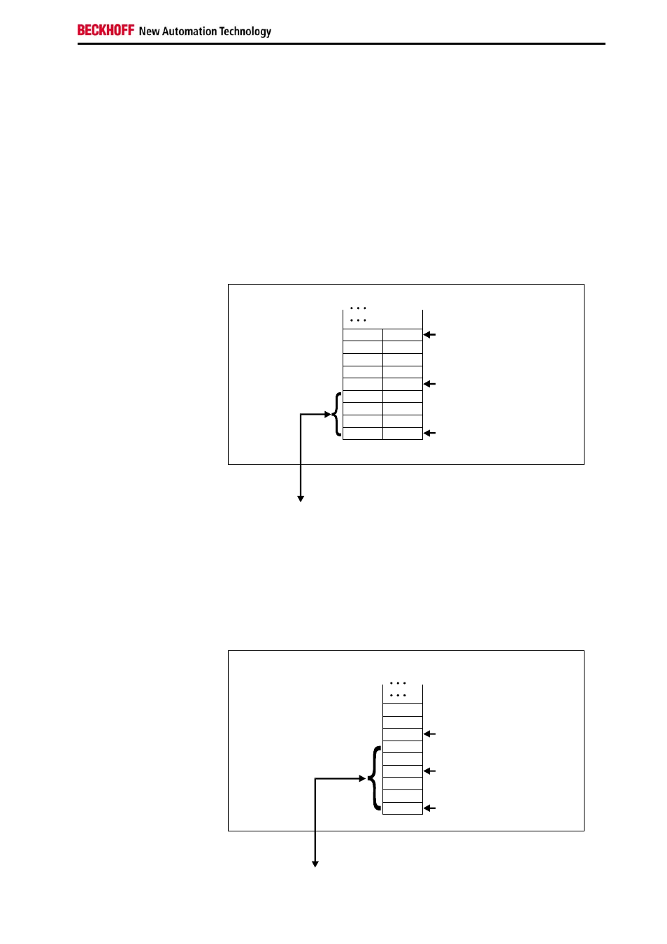
BK2000 Lightbus Coupler
In the BK2000 Lightbus coupler, the control and status byte is mapped in
addition to the data bytes. This is always located in the low byte at the
offset address of the terminal channel.
Example for KL3202:
0
Offset Terminal1 Channel1 = 0
Offset Terminal2 Channel1 = 4
KL3202
Offset Terminal2 Channel2 = 8
User data allocation depending
on mapping
K-Bus
Beckhoff-Lightbus
bus coupler
BK2000
To the bus terminal
L
H
C/S - 0
D0 - 0
D0 - 1
D1 - 0
D1 - 1
C/S - 1
C/S
C/S
Data L
Data H
Data H Data L
C/S
The terminal is
mapped in the
bus coupler.
BK3000 PROFIBUS
coupler
For the BK3000 PROFIBUS coupler, the master configuration should
specify for which terminal channels the control and status byte is to be
inserted. If the control and status byte are not evaluated, the terminals
occupy 2 bytes per channel:
• KL3201: 2 bytes of input data
• KL3202: 4 bytes of input data
• KL3204: 8 bytes of input data
Example for KL3202:
Offset Terminal1 Channel1 = 0
Offset Terminal1 Channel2 = 3
Offset Terminal2 Channel1 = 6
KL 3202 Channel1
KL 3202 Channel 2
The control-/status byte
must be inserted for
parameterization.
K-Bus
Profibus bus coupler
BK3000
To the bus terminal
Data H
Data L
D1 - 0
D0 - 0
D0 - 1
D1 - 1
C/S - 0
C/S
C/S - 1
0
The terminal is
mapped in the
bus coupler.