Functional description – BECKHOFF KL3201 User Manual
Page 9
Functional description
KL3201, KL3202 and KL3204
7
Functional description
The KL320x analog input terminals enable resistance sensors to be
connected directly. A micro-controller within the terminal is used for
converting and linearizing the resistance to a temperature value. The
temperatures are displayed as follows:
• Measuring range 10 to 5000 Ω: 1/2 °C (1 digit = 0.5 °C)
• All other measuring ranges: 1/10 °C (1 digit = 0.1 °C)
In addition to this, a broken wire or short circuit is reported to the Bus
Coupler or to the controller, and indicated by the ERROR LED.
PT100, NI100, PT200, PT500, NI120, NI1000 and PT1000 elements are
implemented over their full measuring ranges as resistance sensors. The
terminal can be fully configured over a fieldbus. A self-defined scaling of
the output can, for instance, be performed, or the temperature conversion
can be switched off. In the latter case, the measurement is output in the
range from 10 Ω up to 1.2 kΩ with a resolution of 1/16 Ω (the internal
resolution of the resistance value is 1/255 Ω).
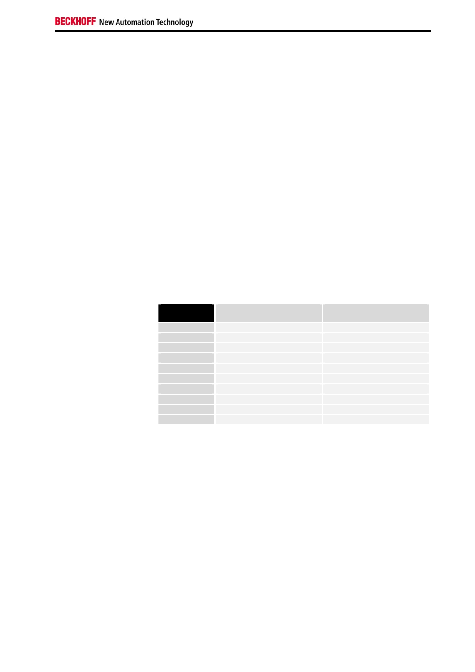
Output format
of the process data
In the delivery state, the measured value is displayed in increments of
1/10° C in two's complement format (integer). The complete measuring
range is output for each resistance sensor. Other display types can be
selected via the feature register (e.g. sign/amount representation, Siemens
output format).
Measured
value
Hexadecimal output
Signed integer output
-250.0°C
0xF63C
-2500
-200.0°C
0xF830
-2000
-100.0°C
0xFC18
-1000
-0.1°C
0xFFFF
-1
0.0°C
0x0000
0
0.1°C
0x0001
1
100.0°C
0x03E8
1000
200.0°C
0x07D0
2000
500.0°C
0x1388
5000
850.0°C
0x2134
8500
Resistance limit values
R > 400 Ω: Bits 1 and 6 (over range and error bits) in the status byte are
set. The linearization of the characteristic curve is continued with the
coefficients of the upper range limit up to the limit stop of the A/D converter
(approx. 500 Ω for PT100).
R<18 Ω: Bits 0 and 6 (under range and error bits) in the status byte are set.
The smallest negative number is displayed (0x8001 corresponds to -
32767).
For over range or under range the red error LED is switched on.
LED display
The LEDs indicate the operating state of the associated terminal channels.
Green LEDs: RUN (not applicable for KL3204)
• On: normal operation
• Off: Watchdog-timer overflow has occurred. If no process data is
transmitted to the bus coupler for 100 ms, the green LEDs go out.
Red LEDs: ERROR
• On: Short circuit or wire breakage. The resistance is in the invalid
range of the characteristic curve.
• Off: The resistance is in the valid range of the characteristic curve.