BECKHOFF KL3201 User Manual
Page 13
Register Description
KL3201, KL3202 and KL3204
11
The main features of the internal data structure are the same for all the
intelligent terminals. This data area is organized as words and comprises
64 registers. The important data and parameters of the terminal can be
read and set through this structure. It is also possible for functions to be
called by means of corresponding parameters. Each logical channel in an
intelligent terminal has such a structure (4-channel analog terminals
therefore have 4 sets of registers).
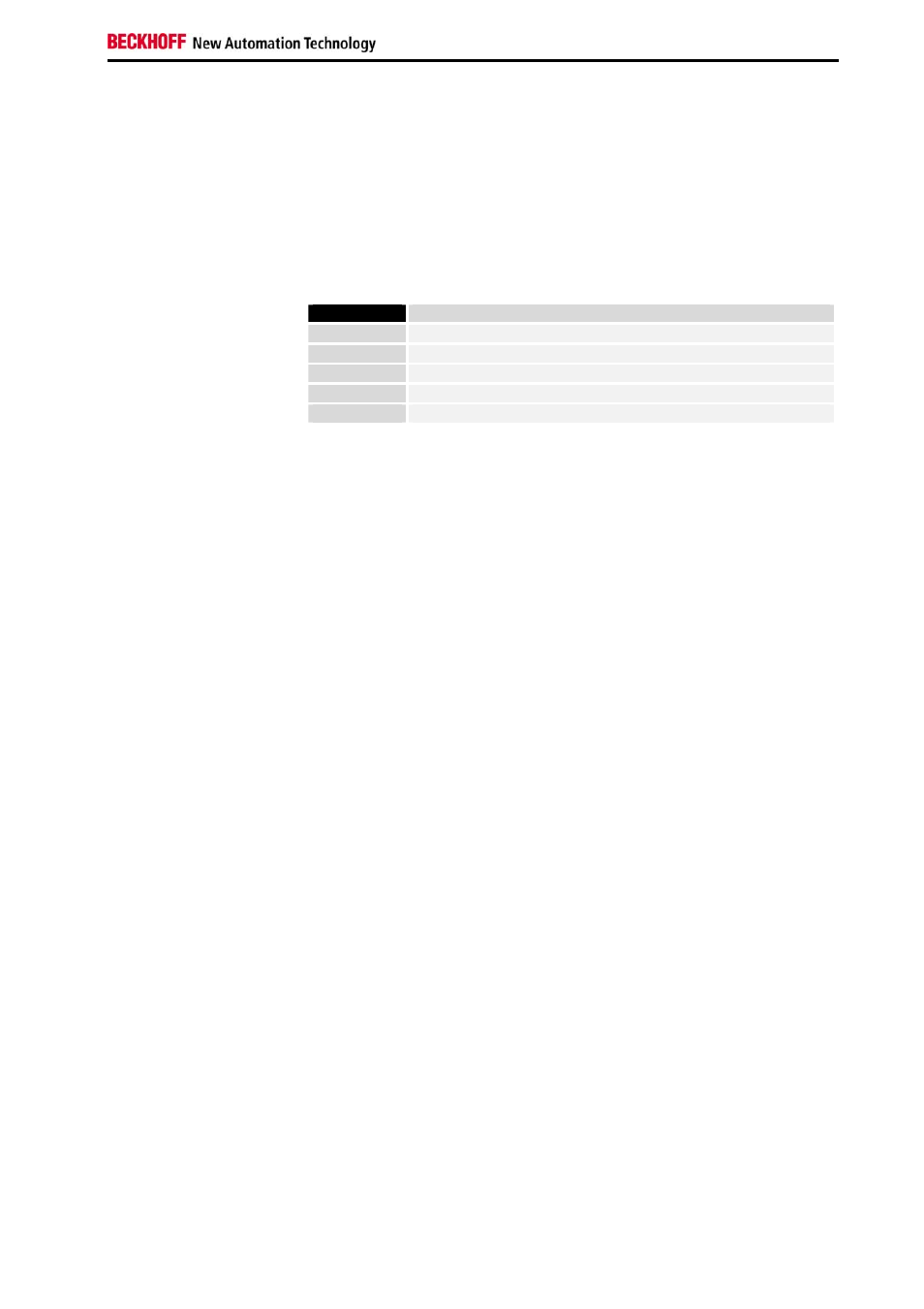
This structure is divided into the following areas:
(A detailed list of all registers can be found in the Appendix.)
Register
Application
0 to 7
Process variables
8 to 15
Type register
16 to 30
Manufacturer parameters
31 to 47
User parameters
48 to 63
Extended user area
Process variables
R0 to R7: Registers in the internal RAM of the terminal:
The process variables can be used in addition to the actual process image.
Their function is specific to the terminal.
R0 to R5: Terminal-specific registers
The function of these registers depends on the respective terminal type
(see terminal-specific register description).
R6: Diagnostic register
The diagnostic register can contain additional diagnostic information. Parity
errors, for instance, that occur in serial interface terminals during data
transmission are indicated here.
R7: Command register
High-Byte_Write = function parameter
Low-Byte_Write = function number
High-Byte_Read = function result
Low-Byte_Read = function number
Type register
R8 to R15: Registers in the internal ROM of the terminal
The type and system parameters are hard programmed by the
manufacturer, and the user can read them but cannot change them.
R8: Terminal type
The terminal type in register R8 is needed to identify the terminal.
R9: Software version (X.y)
The software version can be read as a string of ASCII characters.
R10: Data length
R10 contains the number of multiplexed shift registers and their length in
bits. The Bus Coupler sees this structure.
R11: Signal channels
Related to R10, this contains the number of channels that are logically
present. Thus for example a shift register that is physically present can
perfectly well consist of several signal channels.
R12: Minimum data length
The particular byte contains the minimum data length for a channel that is
to be transferred. If the MSB is set, the control and status byte is not
necessarily required for the terminal function and is not transferred to the
control, if the Bus Coupler is configured accordingly.