BECKHOFF KL6001 User Manual
Page 7
Terminal configuration
KL6001
7
0
Offset Terminal1 = 0
Offset Termianl2 Channel1 = 4
KL6001
Offset Terminal3 Channel1 = 8
User data allocation depending
on mapping.
K-Bus
Beckhoff-Lightbus
bus coupler
BK2000
To the bus terminal
L
H
C/S
Ser. C/S
D0
-
-
-
C/S
C/S
Data L
D1
Data H
D2
Data H Data L
C/S
The terminal is
mapped in the
bus coupler.
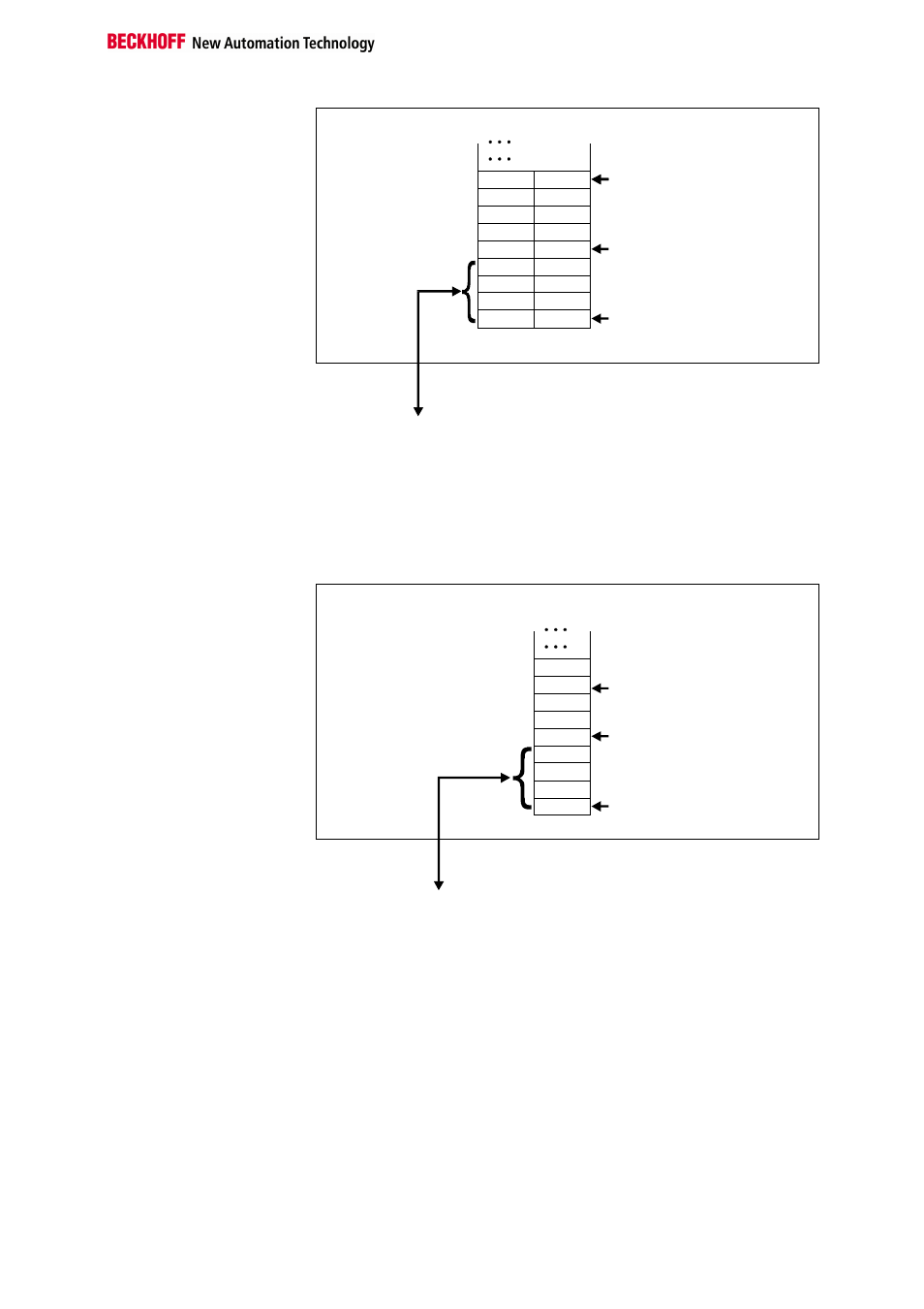
Profibus coupler BK3000
When using the Profibus coupler BK3000, how the KL6001 is to map itself
in the bus coupler is set in the master configuration software. When deliv-
ered, the KL6001 is set to the alternative format. Please pay attention to
the registers 34 and 35 if you wish to set the standard format and a differ-
ent user data length. The figure shows the mapping for 4 bytes of input
data and 4 bytes of output data.
Offset Termianl1 Channel1 = 0
Offset Termial2 Channel1 = 4
Offset Termianl2 Channel2 = 7
KL6001
The control/status byte
must be inserted for
parameterization.
K-Bus
Profibus bus coupler
BK3000
To the bus terminal
Data H
Data H
Data L
D0
D2
D1
D2
Ser.-C/S
C/S
C/S
0
The terminal is
mapped in the
bus coupler.
Interbus coupler BK4000
By default, the Interbus coupler BK4000 maps the KL6001 with 4 bytes of
input data and 4 bytes of output data. Parametrization via the field bus is
not possible. The KS2000 software is needed to redefine the terminal’s
parameters.