Register description, General register description – BECKHOFF KL6001 User Manual
Page 8
Register description
8
KL6001
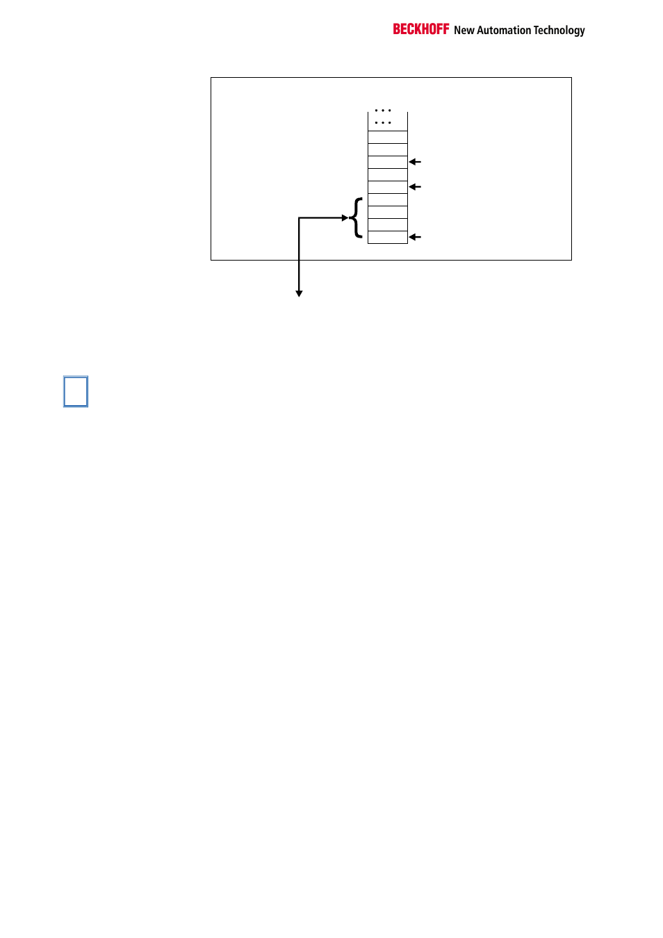
Offset Terminal1 Channel1 = 0
Offset Termianl2 Channel1 = 4
KL6001
Offset Termianl2 Channel1 = 6
The control/status byte
must be inserted for
parameterization (KS2000).
K-Bus
Interbus bus coupler
BK4000
To the bus terminal
D2
D0
Data H
Data H
Data H
Ser.-C/S
D1
Data L
Data L
0
The termianl is
mapped in the
bus coupler.
Other bus couplers and
further information
You will find further information of the mapping configuration of bus cou-
plers in the annex of the respective bus coupler manual under the heading
of "Configuration of Masters".
i
Note
The annex contains an overview of possible mapping configurations de-
pending on the parameters that can be set.
Parametrization with the
KS2000 software
Parametrization operations can be carried out independently of the field
bus system using the Beckhoff KS2000 configuration software via the se-
rial configuration interface in the bus coupler.
Register description
The complex terminals can be adjusted to different operating modes or
functionalities. The " general description of register " describes the con-
tents of the registers, which are identical for all complex terminals.
The terminal-specific registers are explained in the section following to it.
The access to the internal registers of the terminal is described in the sec-
tion " register communication ".
General register description
Complex terminals that possess a processor are capable of bidirectionally
ex-changing data with the higher-level control system. Below, these termi-
nals are referred to as intelligent bus terminals. They include the analog
inputs (0-10V, -10-10V, 0-20mA, 4-20mA), the analog outputs (0-10V, -10-
10V, 0-20mA, 4-20mA), serial interface terminals (RS485, RS232, TTY,
data transfer terminals), counter terminals, encoder interfaces, SSI inter-
faces, PWM terminals and all other parametrizable terminals.
Internally, all intelligent terminals possess a data structure that is identical
in terms of it's essential characteristics. This data area is organized in
words and embraces 64 memory locations. The essential data and pa-
rameters of the terminal can be read and adjusted by way of the structure.
Function calls with corresponding parameters are also possible. Each logi-
cal channel of an intelligent terminal has such a structure (therefore, 4-
channel analog terminals have 4 register sets.