Using the fb1111-0142 in spi- or µc-mode – BECKHOFF FB1111-014x User Manual
Page 14
Process Data Interfaces
8
FB1111 Piggyback Controller Board
3.4
Using the FB1111-0142 in SPI- or µC-Mode
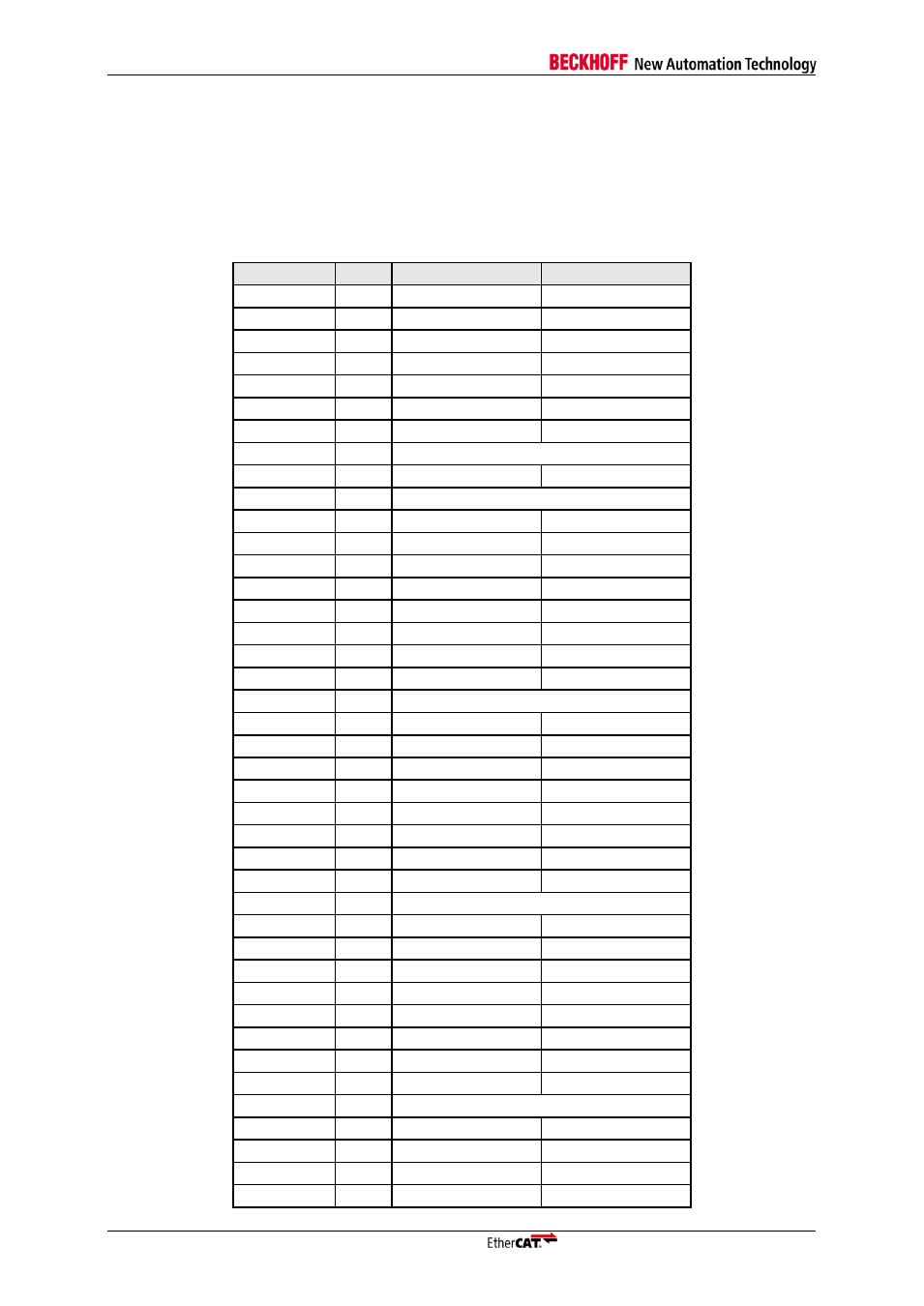
The FB1111-0142 supplies all process data signals of the ET1100 on its PDI connector. Therefore the
FB1111-0142 can be configured to operate in SPI- or µC-Mode. In these cases the pinout of the
FB1111-0142 differs from the other piggyback controller board variants. The following table (Table 7)
shows the signal definitions on the FB1111-0142s PDI connector.
Table 7 Pinout of the FB1111-0142 in SPI and µC Mode
Pin number
Port
SPI
16bit as. µC
1
GND
GND
2
PA0
SPI_CLK
CS
3
PA1
SPI_SEL
RD
4
PA2
SPI_DI
WR
5
PA3
SPI_DO
BUSY
6
PA4
SPI_IRQ
IRQ
7
PA5
N.C.
BHE
8
PA6
EEPROM Loaded
9
PA7
N.C.
ADR[15]
10
GND
11
PB0
GPO[0]
ADR[14]
12
PB1
GPO[1]
ADR[13]
13
PB2
GPO[2]
ADR[12]
14
PB3
GPO[3]
ADR[11]
15
PB4
GPI[0]
ADR[10]
16
PB5
GPI[1]
ADR[9]
17
PB6
GPI[2]
ADR[8]
18
PB7
GPI[3]
ADR[7]
19
GND
20
PC0
GPO[4]
ADR[6]
21
PC1
GPO[5]
ADR[5]
22
PC2
GPO[6]
ADR[4]
23
PC3
GPO[7]
ADR[3]
24
PC4
GPI[4]
ADR[2]
25
PC5
GPI[5]
ADR[1]
26
PC6
GPI[6]
ADR[0]
27
PC7
GPI[7]
DATA[0]
28
GND
29
PD0
GPO[8]
DATA[1]
30
PD1
GPO[9]
DATA[2]
31
PD2
GPO[10]
DATA[3]
32
PD3
GPO[11]
DATA[4]
33
PD4
GPI[8]
DATA[5]
34
PD5
GPI[9]
DATA[6]
35
PD6
GPI[10]
DATA[7]
36
PD7
GPI[11]
CPU_CLK_IN
37
GND
38
PE0
GPO[15]
DATA[11]
39
PE1
GPO[14]
DATA[10]
40
PE2
GPO[12]
DATA[8]
41
PE3
GPI[14]
DATA[14]