Component placement specification, Placed/unplaced components, Power test pads – BECKHOFF FB1111-014x User Manual
Page 16: Table 8: power test pads, Figure 3: example for placed/unplaced components, Er 4
Component Placement Specification
10
FB1111 Piggyback Controller Board
4
Component Placement Specification
In the following chapters the component placement specification in terms of reference designators and
component values are listed for the three variants of the FB1111 EtherCAT piggyback controller
board.
4.1
Placed/Unplaced Components
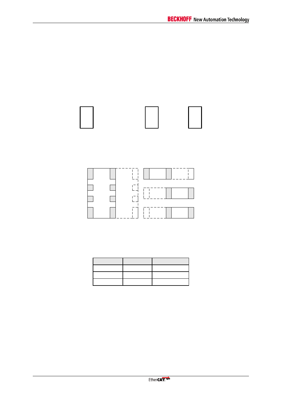
As the variants of the FB1111 are all based on one printed circuit board, the different PDI configura-
tions are achieved by alternative component placements. Figure 3 is an example for placed and un-
placed components. Designators for placed components are surrounded by a rectangle. Components
that are not mounted for a specific variant are also referenced by a designator, but without the sur-
rounding rectangle.
R
5
0
0
R
5
0
1
R
5
0
2
R
5
0
3
R
5
0
4
R
5
0
5
Figure 3: Example for placed/unplaced components
Most of the resistor pairs within the PDI configuration area are sharing one pad with each other. When
modifying the resistor configuration care have to be taken in order to connect the corresponding pads
with each other correctly. An example is shown in Figure 4 for single resistors as for an resistor net-
work.
R
N
5
0
1
R
N
5
0
0
R500
R501
R503
R502
R505
R504
Figure 4: Pads of resistor networks and single resistors
4.2
Power Test Pads
Table 8: Power Test Pads
Designator
Signal
Connected To
TP800
+2.5V Core ET1100
TP604
+3.3V
+3.3V
TP605
GND
GND