Overview, Indicator leds, Variant differentiation – BECKHOFF FB1111-014x User Manual
Page 9: Table 1: indicator leds, Table 2: variants of the fb1111-014x, Figure 1: overview of the fb1111-014x, Port 0, Pdi configuration area pdi connector out, Port 1
Overview
FB1111 Piggyback Controller Board
3
2
Overview
The EtherCAT Piggyback controller boards FB1111-014X combine an ET1100 EtherCAT Slave Con-
troller, two EtherCAT ports and a PDI-Connector on a printed circuit board. The Piggyback controller
boards can as well be used for EtherCAT evaluation purposes as assembled into customer end prod-
ucts. Three variants with different Process Data Interfaces (PDIs) are existing in order to cooperate
with the most commonly known hardware interfaces like digital IO, SPI and Microcontroller.
IN
TR 0
ET1100
+5V
RUN
Port 0
E
²P
Link 1
Link 0
PHY
0
PDI Configuration
Area
PDI Connector
OUT
TR 1
Port 1
PHY
1
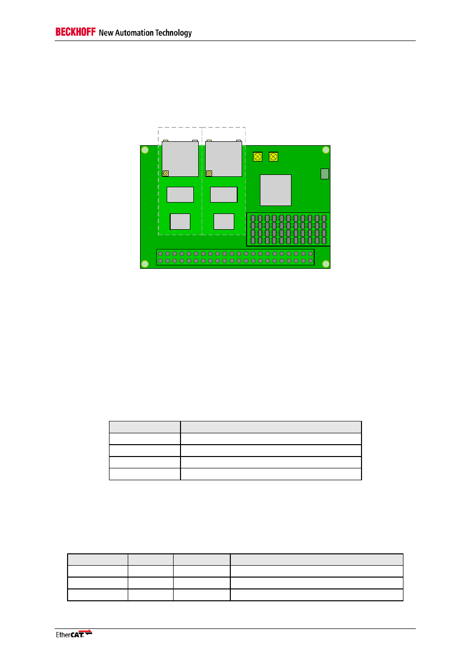
Figure 1: Overview of the FB1111-014X
The board is structured in areas for Port 0 and Port 1, the PDI Connector, a PDI Configuration Area,
EEPROM, LEDs, and the ET1100 EtherCAT Slave Controller. While the EtherCAT port configuration,
LEDs, ET1100 and EEPROM are identical for the different variants of the FB1111-014X, the PDI Con-
figuration Area differs in order to achieve different PDI Connector pinouts. Each EtherCAT port in Fig-
ure 1 combines a PHY, magnetics and an RJ45 connector. The PDI Configuration Area is a field of
resistors. Different pinouts on the PDI connector can be achieved by different resistor combinations in
this area. (See chapter 3.)
2.1
Indicator LEDs
Four LEDs for information about the device status are available on all three variants of the FB1111.
Table 1 is giving an overview over the indicator LEDs on the PCB.
Table 1: Indicator LEDs
LED
Comment
+5V
Indicates 5V power supply
RUN
RUN indicator (LED) for application state
Link 0
Link/Act Indicator (LED) for port 0
Link 1
Link/Act Indicator (LED) for port 1
2.2
Variant Differentiation
The three variants of the FB1111-014X are corresponding to three different PDI configurations. The
type of PDI interface can be identified by the last position in the product code. In Table 2 the variants
of the FB1111-014X are listed with respect to the different PDI interfaces.
Table 2: Variants of the FB1111-014X
Product Code Sub Code PDI Interface
Comment
FB1111
0140
µController
16/8 bit asynchronous Microcontroller Interface
FB1111
0141
SPI
Serial Peripheral Interface (Slave)
FB1111
0142
Digital IO
32 bit In/Out digital interface