2 starting up – Bronkhorst LIQUI-FLOW mini (till 01-07-2013) User Manual
Page 6
9.17.065
page 6
2 Starting
up
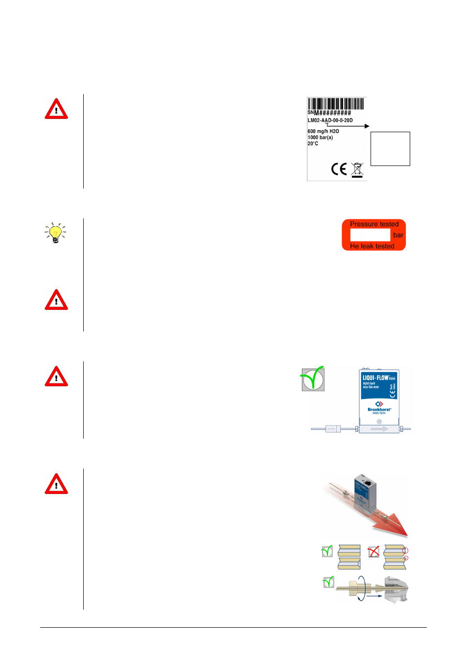
2.1 Check properties
Before installing your Mass Flow Meter it is important to
read the attached labels and check:
- Flow rate
- Pressure
- Fluid to be measured
- Output signal
- Temperature
2.2 Rated pressure test inspection
Each LIQUI-FLOW mini instrument is pressure tested to at least 1.5 times
the working pressure of the process conditions stipulated by the customer.
Pressure testing label
Each instrument is helium leak tested to at least 2
⋅
10
-9
mbar l/s Helium
outboard.
The tested pressure is stated on the instrument with a RED COLOURED sticker. Before installation, make
sure that the test pressure is in accordance with normal safety factors for your application.
If there is no Pressure Testing Sticker on the device or if the test pressure is incorrect, the instrument
should not be mounted in the process line and be returned to the factory.
2.3 Check piping
For reliable measurement always make sure the fluid stream
is clean.
Use filters to assure a particle-free liquid stream.
Recommended pore-size: 2 µm.
If back flow can occur, a downstream filter is recommended too.
2.4 Install system
Install the LIQUI-FLOW mini Meter in the line, in accordance with
the direction of the FLOW arrow. The arrow for flow direction is
indicated on the body of the instrument.
Make sure to use 10-32 UNF fittings (ferrules/nuts) and tubing
suitable for the maximum applied system pressure. Only use 1/16”
tubing with a straight and clean cut without burrs to ensure leak
tightness. Preferrably deburr the tubing prior to installation. A new
ferrule connection must be made for each new adapter to ensure
leak-tightness and minimum dead volume, due to variances in the
adapter dimensions.
Tighten the 10-32 UNF fittings according to the instructions of the
supplier of the fittings.
Output
A – 0…5 Vdc
B – 0…10 Vdc
F – 0…20 mA
G – 4…20 mA
1500