Dpr-901ii – BSS Audio DPR-901II Owner's Manual User Manual
Page 22
2 2
DPR-901ii
There are several options available on the connection between the input
XLR pin 1, and the chassis, and the optimum configuration will depend
upon the installation, and the equipment it is connected to.
For the main input, positions LK1 and C1 are provided. The factory
default is LK1 not fitted, and C1 is 100pF.
For the split input, positions LK6 and C52 are provided. The factory
default is LK6 not fitted, and C52 is 100pF.
A2 Input pin 1 to
Chassis Connection
Input pin 1 to Chassis Connection
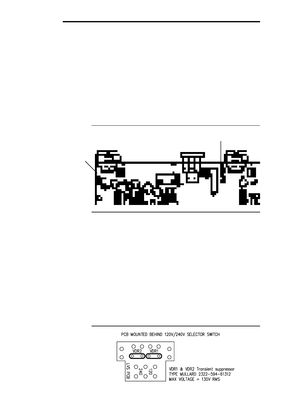
Transient Suppressor Replacement
The primary of the mains transformer within the DPR-901ii is protected
against high voltage spike interference by two voltage dependent resis-
tors. These provide a short circuit to voltage peaks in excess of their
maximum rating.
Should the DPR-901ii be inadvertently connected to 3 phase line/line
voltages, or to 240V when selected to 120V, or any other incorrect
voltage, these suppressors are likely to fail in a protective short circuit
mode. This will be demonstrated by repeated mains fuse failure when
powering up the unit.
Even in this case of extreme overvoltage, the DPR-901ii is protected
against failure, and the simple removal of these suppressors will allow
the unit to be used again. However, it is important that they are re-
placed as soon as possible to ensure continued protection.
Figure A3.1 indicates the location and specification for the suppressors.
A3 Transient
Suppressor
Replacement
A3.1 Suppressor
location
Split input Chassis
Connection
Main input Chassis
Connection
A2.1 Chassis Links