Caple C621 User Manual
Page 14
Page 14
C621 C721 user manual.DOC
INJECTORS TABLE
Cat II 2H3+ NOMINAL
POWER
REDUCED
POWER
G30/G31
28-30/37 mbar
G20
20 mbar
BURNERS
[Hs - Kw]
[Hs - Kw]
Injector dial.
[1/100 mm]
Burners with
Safety valve device
Burners without
safety valve device
Injector dial.
[1/100 mm]
By-pass [1/100
mm]
By-pass [1/100 mm] By-pass [1/100 mm]
Semi-rapid (SR) 1,75
0,45
65
30
34
97
Adjustable
Rapid (R)
3,00
0,75
85
40
44
115
Adjustable
Triple ring (TR) 3,50
1,50
95
62
65
135
Adjustable
OPERATIONS TO BE PERFORMED WHEN SUBSTITUTING THE INJECTORS
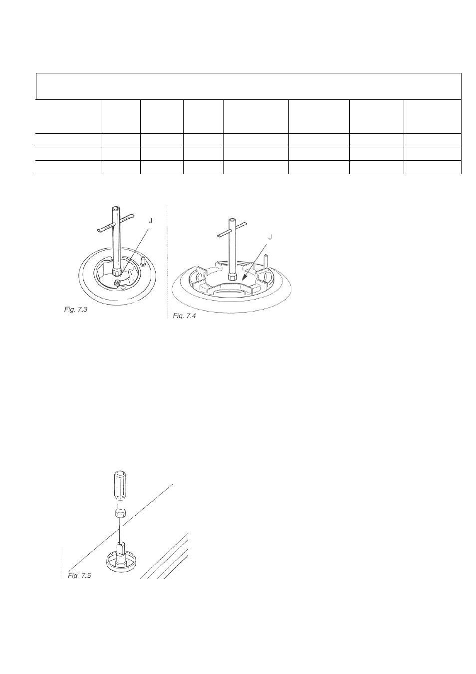
• Remove the gratings, the
burner covers and the
knobs;
• Using a wrench, substitute
the nozzle injectors "J"
(Fig. 7.3 - 7.4) with those
most suitable for the kind
of gas for which it is to be
used.
The burners are made in such a way so as not to require the regulation of the
primary air.
REGULATING THE BURNER MINIMUM SETTING
When switching from one type of gas to another, the minimum flow rate must also be cor-
rect: the flame should not go out even when passing suddenly from maximum to minimum
flame.
To regulate the flame follow the instructions below:
• Light the burner
• Set the cock valve to minimum
On gas valves provided with adjustment screw in
the centre of the shaft (fig. 7.5):
• Using a screwdriver with max. diameter 3 mm, turn
the screw inside the tap until the correct setting is
obtained.