6 microphone input, 1 paging access contacts – Cloud Electronics CX263 User Manual
Page 11
6 Microphone Input
Two microphone inputs are provided with electronically balanced, transformer-less circuitry configured
for optimum low noise performance. The input impedance is greater than 2k
Ω
and suitable for
microphones in the 200
Ω
to 600
Ω
range. Input is via the 3-pin plug in screw terminal type connector
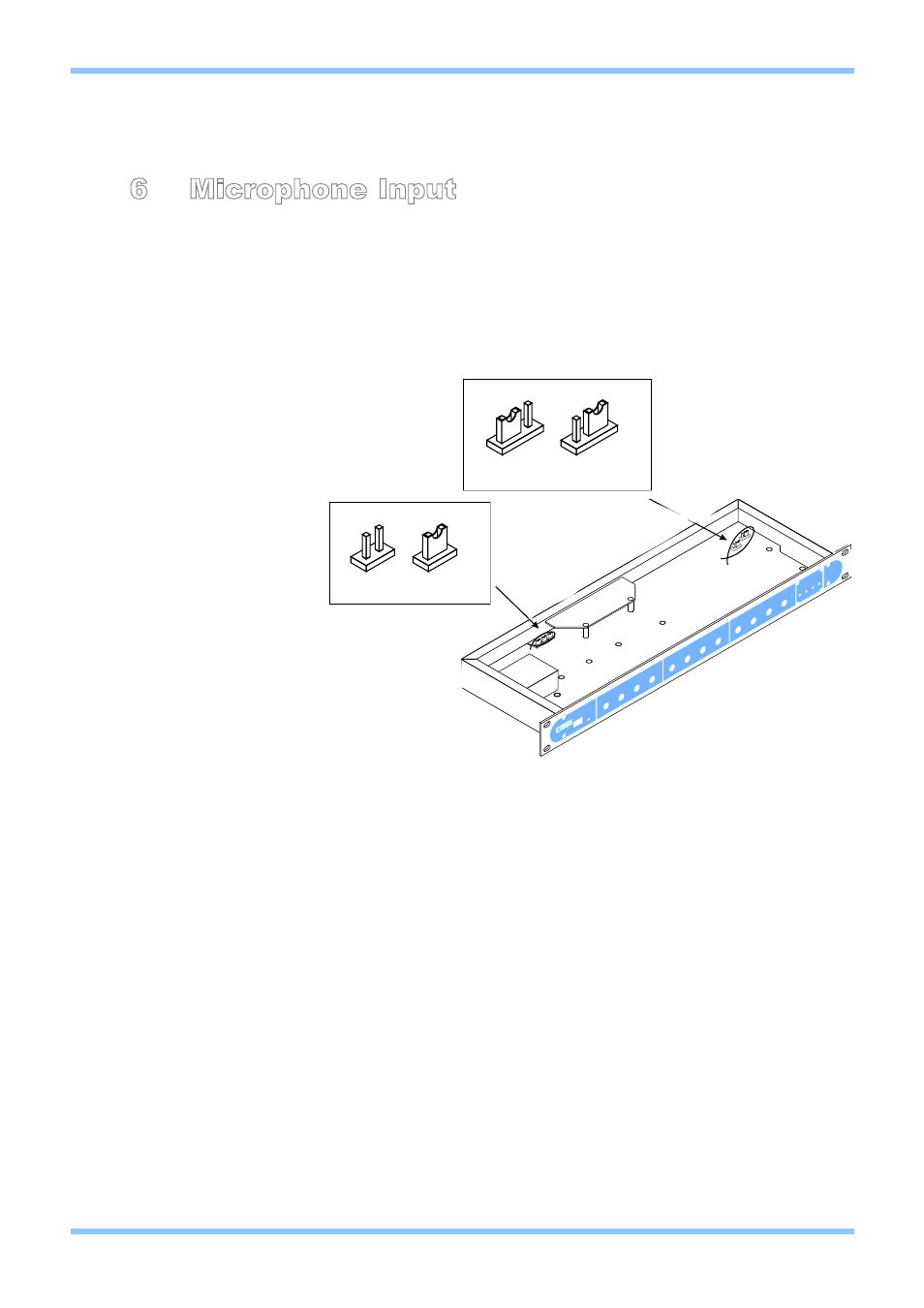
(Phoenix type) located on the rear panel. A facility to provide 15V phantom power is included that is
activated by setting the internal jumpers J1 (Mic 1) or J2 (Mic 2) to the ‘ON’ position.
Microphone inputs follow the balanced audio pin convention shown below:
Pin 1 - GROUND
Pin 2 - COLD
Pin 3 - HOT
When setting the jumper please ensure that you:
• Remove the mains cable from the rear of the product before removing the top panel.
• Only reassemble the unit using screws identical to the original parts.
6.1 Paging Access Contacts
Access contacts for the microphone 1 input signal are provided to control which zones the
microphone will be active in. This provides the facility for paging microphones, such as the
Cloud CPM-4, to be connected to the CX263. The access contacts work on a short-to-ground
system, which is compatible with the majority of paging microphones. If the microphone 1 input
is to be used with standard microphones, the contacts can be bypassed via the configuration
of the internal jumpers detailed below:
J4-6: Zones 1-3 respectively
Note: We advise that when you remove a jumper you leave it connected to one pin of the
header so it remains with the apparatus for future use.
Upon leaving the factory, the unit is configured to bypass the microphone access contacts. In
order to activate the access contact for a particular zone, the appropriate link will need to be
removed.
CX263 Zone Mixer
Installation and Setup Guide
CLOUD ELECTRONICS LIMITED
5
V2 100904
CX263
ON
OFF
J1-2 SETTINGS
ACC
BYP
J4-6 SETTINGS