7 output details, 8 remote music mute - fire alarm interface – Cloud Electronics CX263 User Manual
Page 14
7 Output Details
Each output terminal is balanced, using a
3 pole ‘Phoenix’ type connector that can
operate into loads as low as 1k2
Ω
. The
nominal output level is 0dBu (775mVrms)
but the mixer can operate with a wide
range of signals up to a maximum output
level of +20dBu (7.75Vrms). For balanced
interconnections, 2-core screened cable
should be used. Connect the screen to pin
1, the reverse phase signal (normally blue
or black) to pin 2 and the in-phase signal
(normally red) to pin 3. If you wish to
connect any zone output to an unbalanced
input, connect the cable screen to pin 1
with the hot connection (inner core) to pin
3 and make no connection to pin 2.
Note that unbalanced signals should not
be run over long distances. It is recommended that you only use unbalanced connections between
pieces of equipment that are in the same rack.
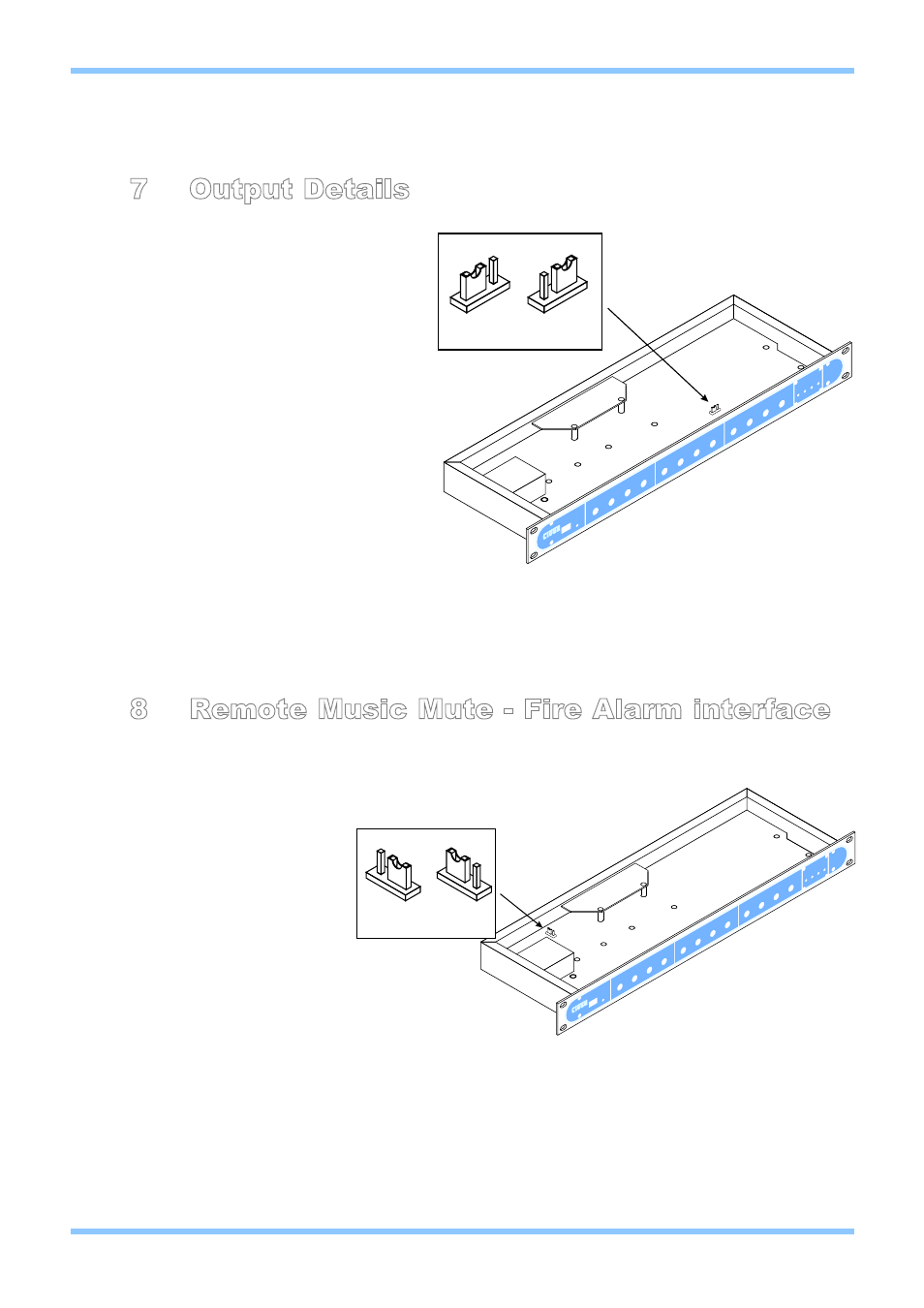
The stereo zone on the CX263 (Zone 1) can be configured to run in mono. When the zone is configured
to run in mono, both left and right outputs from the zone will present the same summed mono signal.
Zone 1 is set to run in stereo by default, but this can be changed via internal jumper J11.
8 Remote Music Mute - Fire Alarm interface
In certain installations, such as licensed premises or retail outlets within a shopping mall, there may be
a local authority or fire service requirement to mute the music signals via a fire alarm control panel in an
alarm condition. The CX263
provides a facility to mute the
music signals only, by using a
fully isolated pair of contacts.
This is usually a relay mounted
close to the CX263, which is
powered by the fire alarm
control panel. The relay can
either be closed or opened in
an alarm condition, but the
internal jumper J7 must be set
to the corresponding position:
• N/C: Normally closed means that alarm condition is when the relay opens.
• N/O: Normally open means that alarm condition is when the relay closes.
When setting the jumper(s) please ensure that you:
• Remove the mains cable from the rear of the product before removing the top panel.
• Only reassemble the unit using screws identical to the original parts.
Upon leaving the factory, the unit is configured for a normally open relay connection.
CX263 Zone Mixer
Installation and Setup Guide
CLOUD ELECTRONICS LIMITED
8
V2 100904
CX263
STEREO
MONO
J11 SETTINGS
CX263
N/C
N/O
J7 SETTINGS