3 music equalisation, Remote control of music – Cloud Electronics CX263 User Manual
Page 9
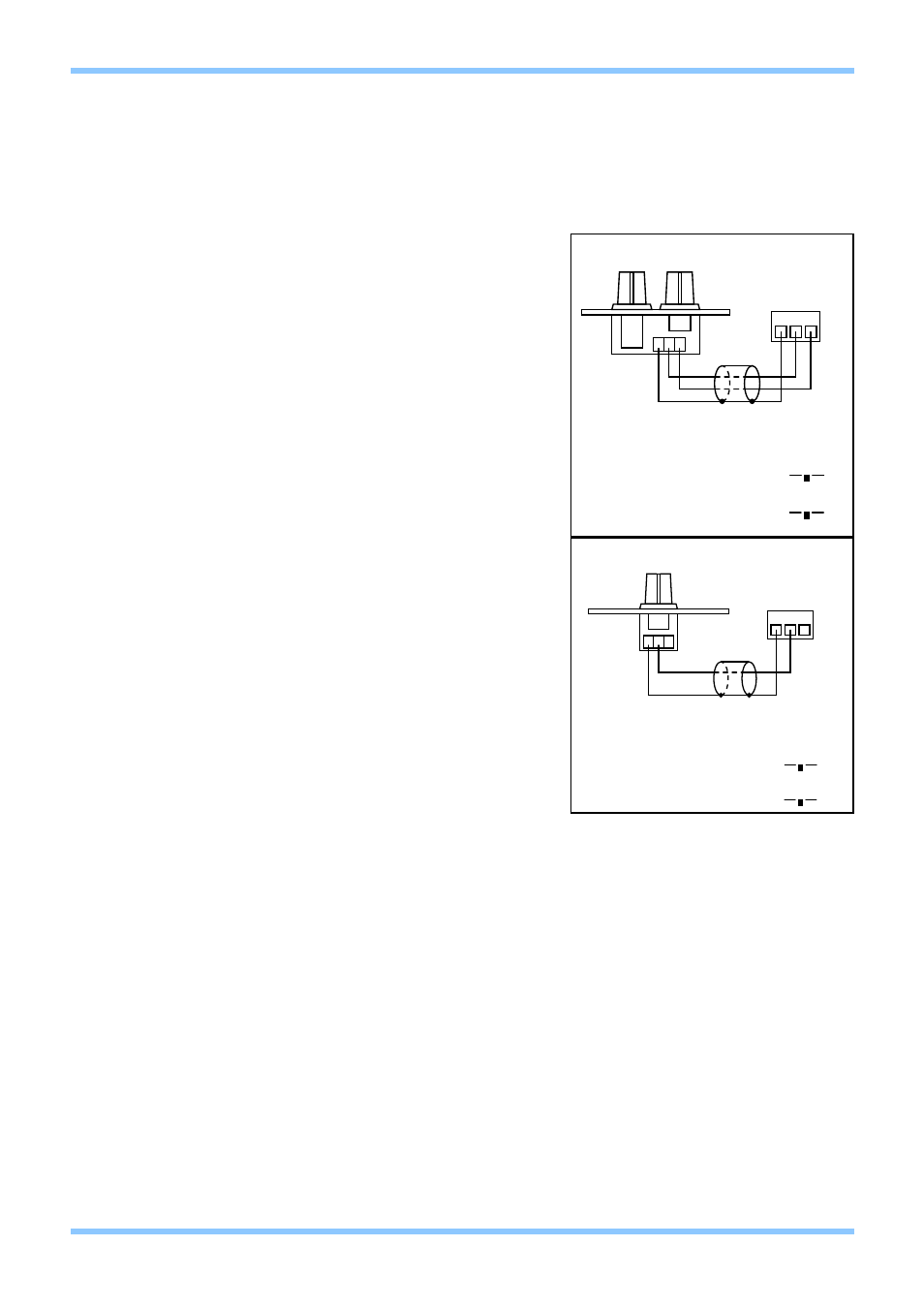
5.2 Music source and level controls - Local or Remote
The music level control function can be controlled
from either the front panel, or a remote control plate
located up to 100m from the CX263. The CX263 is
compatible with the RSL-6 and RL-1 analogue
remote control wallplates. The CX263 is also
compatible with the CDI-S200 serial interface
module (see section 9.1 for installation details). Both
analogue remote control plates can be mounted onto
a standard British flush or surface mounted 25mm
deep back box. Two-core cable with overall screen
should be used to connect the remote controls to the
Cloud CX263 the diagrams above show how to
connect the two remote plates. To configure a zone
to operate with an analogue remote wallplate (such
as the RSL-6) the switches located next to the
remote plate connector on the rear panel need to be
in the ‘REM’ (in) and ‘AN’ (in) positions respectively.
Self-adhesive labels (supplied) can be affixed to the
tamperproof facia and/or RSL-6 to identify the
available input sources.
To connect a RL-1 plate to one zone of the CX263,
the unit must be internally configured to route the
source selection functionality to either the front panel
control, or to the CDI-S200 serial interface module.
This can be done by setting jumpers J19-24 (see
section 9.1 for jumper locations). Remote units
should be connected as shown in these diagrams.
The RSL-6A and RL-1A wallplates are available for
the American market. The operation of these
remotes is identical to their European counterparts,
but they have been designed to fit a single gang US electrical outlet box. Front panel
dimensions are 4½” x 2¾”.
When setting the jumper(s) please ensure that you:
• Remove the mains cable from the rear of the product before removing the top
panel.
• Only reassemble the unit using screws identical to the original parts.
5.3 Music Equalisation
Equalisation for the music signals treble and bass is provided via the rear panel pre-set controls
in order to allow the installer to tailor the response of the music signals to suit the acoustics and
speakers of each individual zone. The equalisation controls for each output are on the rear
panel to the right of the respective output connector(s); they are clearly marked ‘HF’ (High
Frequency) and ‘LF’ (Low Frequency). A flat frequency response can be achieved by
positioning the slots on the control shafts either in the horizontal plane (for stereo zones) or the
vertical plane (for mono zones); the HF control has a range of ±10dB at 10kHz and the LF
control has a range of ±10dB at 50Hz.
CX263 Zone Mixer
Installation and Setup Guide
CLOUD ELECTRONICS LIMITED
3
V2 100904
STANDARD WIRING CONVENTION
USE TWO CORE SCREENED CABLE
SWITCH MARKED ‘FR/REM’ SHOULD
BE SET TO THE ‘REM’ POSITION
SWITCH MARKED ‘DIG/AN’ SHOULD
BE SET TO THE ‘AN’ POSITION
REMOTE CONTROL OF MUSIC LEVEL
FR/REM
REMOTE (IN)
DIG/AN
ANALOGUE (IN)
1
2
3
3 POLE
CONNECTOR
1 2 3
RL-1
STANDARD WIRING CONVENTION
USE TWO CORE SCREENED CABLE
SWITCH MARKED ‘FR/REM’ SHOULD
BE SET TO THE ‘REM’ POSITION
SWITCH MARKED ‘DIG/AN’ SHOULD
BE SET TO THE ‘AN’ POSITION
REMOTE CONTROL OF MUSIC
FR/REM
REMOTE (IN)
DIG/AN
ANALOGUE (IN)
1
2
3
3 POLE
CONNECTOR
1 2 3
RSL-6