Codan Radio Radio Repeater Systems Training Guide User Manual
Page 21
RADIO REPEATER SYSTEM | TRAINING GUIDE
Chapter 2: Repeater System Confi gurations Page 13
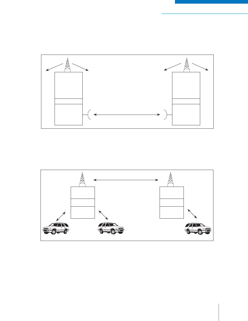
Microwave equipment can be used to link repeaters together instead of radio links as shown in Figure
2-5. E&M is the typical standard used to interface the microwave with the repeater. With this type of
system your site locations are limited to sites where a leased microwave channel is available.
Figure 2-5: Microwave Linked System
Dual-tone, multi-frequency (DTMF) equipment can be added to your repeater(s) to disable its operation
until it is activated by the mobile or base station as shown in Figure 2-6. In this way linking frequencies
are not used until needed, reducing power consumption and possible interference.
Figure 2-6: DTMF Controlled Link System
Without connecting the drops to the links via DTMF, mobile (A) and (B) (above) can communicate with
each other but not to mobile (C). Once both link repeaters are connected to their drops, all three can
communicate with each other.
Drop
repeater
Tx-F3
Rx-F4
Tx-F1
Rx-F2
Interface
Interface
Drop
repeater
Microwave
system owned
by others
Microwave
system owned
by others
Mobile (A)
Mobile (B)
Mobile (C)
Link
Repeater
DTMF
Drop
Repeater
Link
Repeater
DTMF
Drop
Repeater