Azimuth pattern - omni, Figure 3-2: phased dipole array antennas – Codan Radio Radio Repeater Systems Training Guide User Manual
Page 30
TRAINING GUIDE | RADIO REPEATER SYSTEM
Chapter 3: Repeater System Equipment
Page 22
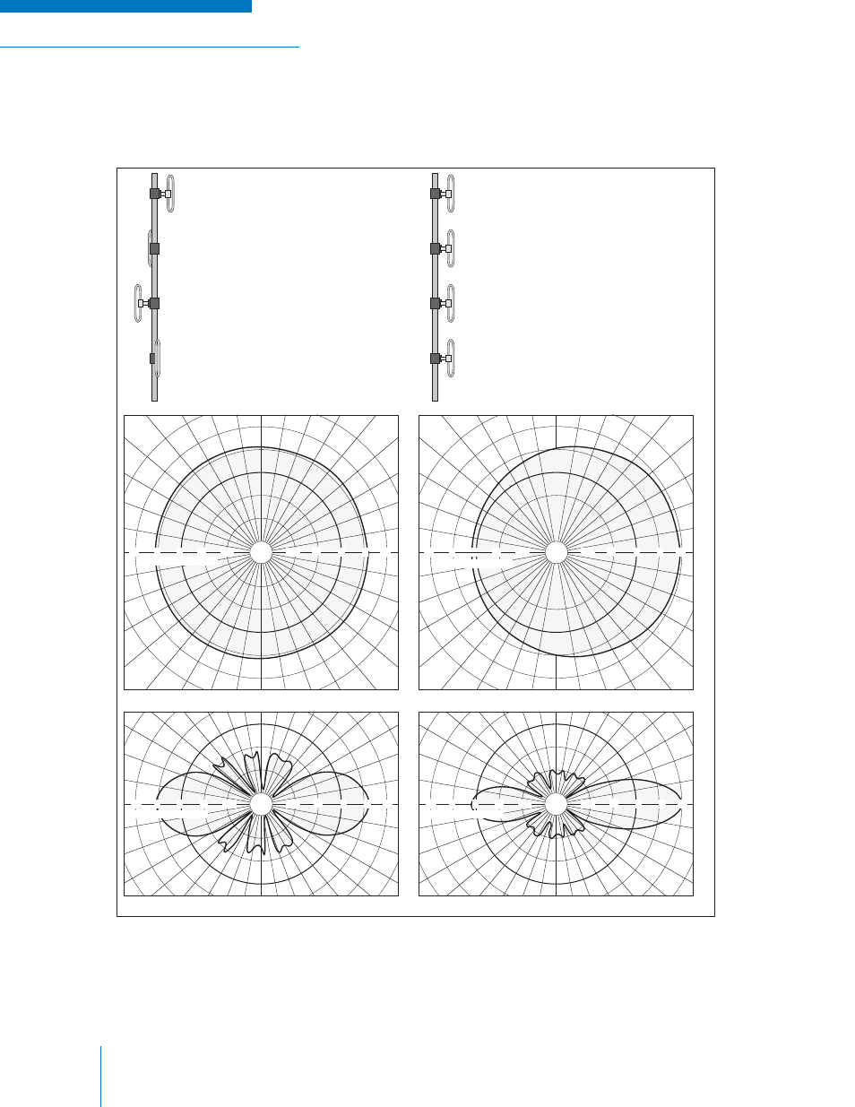
The antennas in Figure 3-2 are “phased dipole arrays” and will provide increased gain in an omni-
directional or offset pattern. They are usually used for local coverage or “drop” purposes.
Figure 3-2: Phased Dipole Array Antennas
dB RE
l /2 DIPOLE
0
-10
-5
0
5
10
-10
-5
5
10
+10°
0
-10°
+10°
0
-10°
-10
-5
0
5
10
-10
-5
0
5
10
dB RE
l /2 DIPOLE
-10
-5
0
5
10
-10
-5
0
5
10
Azimuth pattern - OMNI
+10°
0
-10°
+10°
0
-10°
-10
-5
0
5
10
-10
-5
0
5
10
dB RE
l /2 DIPOLE
Vertical pattern - OMNI
FOUR BAY 150 MHz OMNI
dipole array with typical
azimuth and vertical radiation
patterns shown directly below
FOUR BAY 150 MHz OFFSET
dipole array with typical azimuth
and vertical radiation patterns
shown directly below
Vertical pattern - OFFSET
Azimuth pattern - OFFSET
dB RE
l /2 DIPOLE