Typical horizontal radiation pattern, Corner reflector, Figure 3-3: yagi antenna – Codan Radio Radio Repeater Systems Training Guide User Manual
Page 31: Figure 3-4: corner refl ector antenna
RADIO REPEATER SYSTEM | TRAINING GUIDE
Chapter 3: Repeater System Equipment Page 23
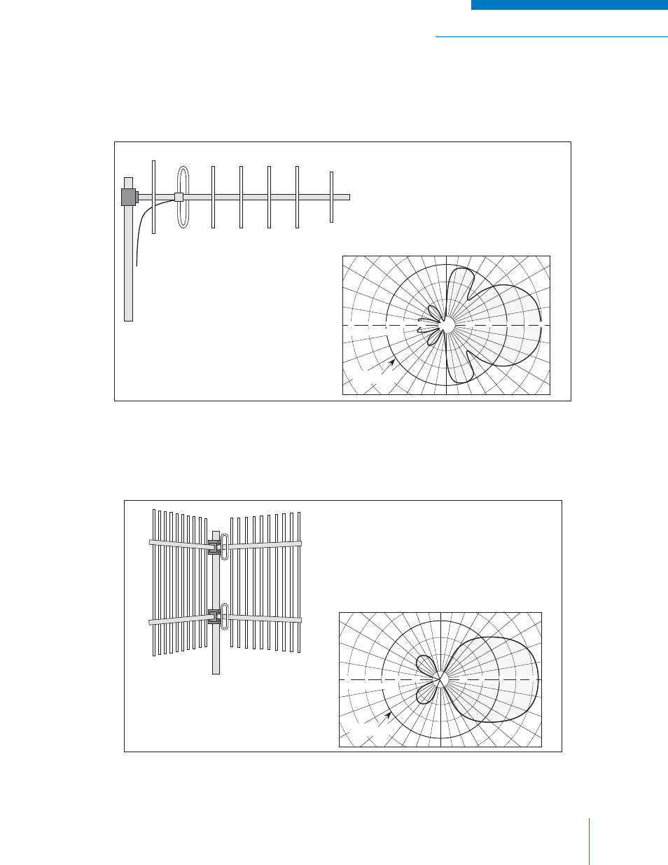
The antenna in Figure 3-3 is a “beam” or “yagi” and is usually used for linking purposes. You may see it
polarized in a horizontal or vertical position. A VHF yagi will be larger than a UHF yagi. A yagi provides
increased gain in one direction. A typical pattern is also illustrated.
Figure 3-3: Yagi Antenna
Another type used on links where a higher front-to-back ratio is required is the corner refl ector antenna
shown in Figure 3-4.
Figure 3-4: Corner Refl ector Antenna
Examples of antenna data and radiation patterns can be found in Appendix F.
Typical Horizontal Radiation
Pattern For Vertical Polarization
BEAM ANTENNA
+10°
0
-10°
DIPOLE
REFERENCE
dB RE
l /2 DIPOLE
-10
-5
0
5
10
-10
-5
0
5
10
Typical Horizontal Radiation
Pattern.
+10°
0
-10°
CORNER REFLECTOR
DIPOLE
REFERENCE
dB RE
l /2 DIPOLE
-10
-5
0
5
10
-10
-5
0
5
10