4 utility connector group, 1 ‘term’ connector, 2 ‘fe’ (fast ethernet) connector – Comtech EF Data CDM-800 User Manual
Page 44: Redundancy’ connector, 3 ‘redundancy’ connector
CDM-800 Gateway Router
Revision 1
Rear Panel Connections
MN-CDM800
3–8
3.2.4
Utility Connector Group
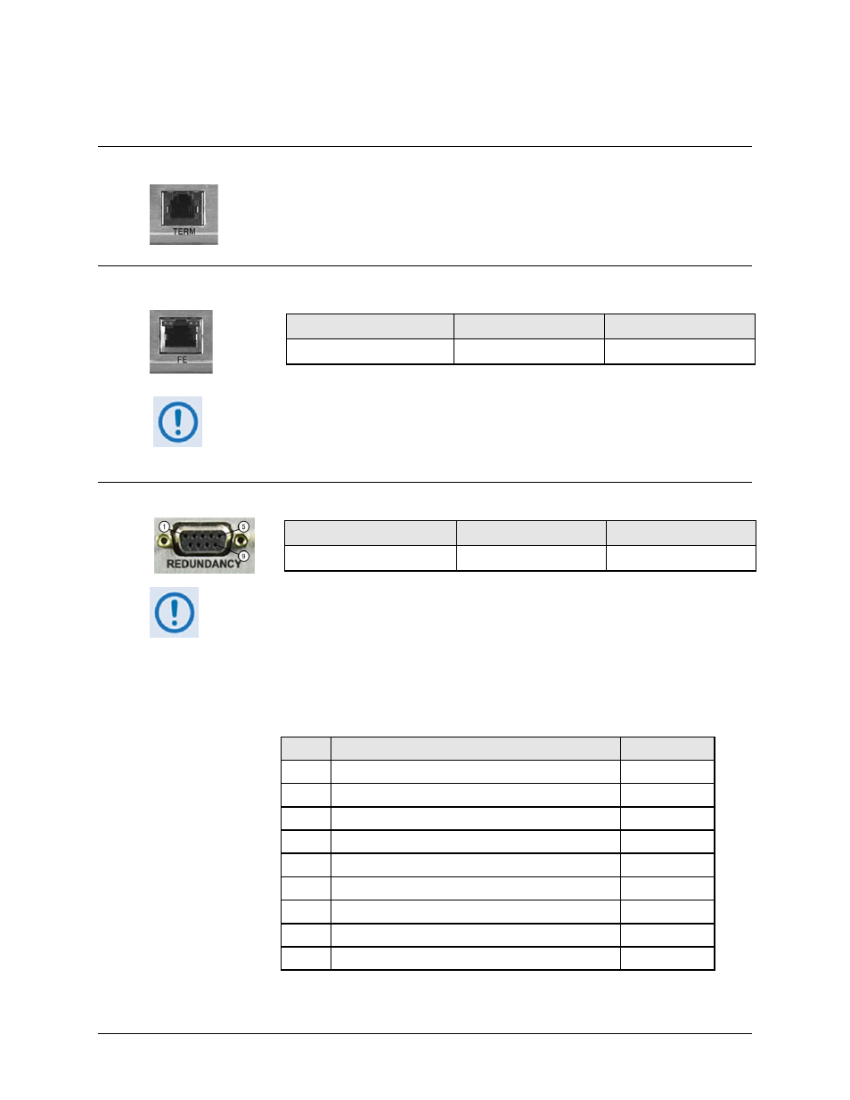
3.2.4.1 ‘TERM’ Connector
This RJ‐12 female modular jack is unused at this time.
3.2.4.2 ‘FE’ (Fast Ethernet) Connector
• This interface operates at 10/100 Mbps, half and full duplex, auto‐negotiating.
• The maximum Ethernet packet size is 1522 bytes (including Ethernet headers and
CRC)
3.2.4.3 ‘REDUNDANCY’ Connector
Connector Type
Name
Direction
Type ‘D’ 9‐pin female
REDUNDANCY
In/Out
This interface is used for connection to an optional CEFD CRS‐170A 1:1 Redundancy
Switch for L‐Band operation, or the CRS‐180 1:1 Redundancy Switch for 70/140 MHz
operation.
M:N device redundancy support is available with the separately purchased Vipersat
Management System (VMS).
Table 3-1. REDUNDANCY Connector Pinout
Connector Type
Name
Direction
RJ‐45 female modular jack
FE
In/Out
PIN #
DESCRIPTION
DIRECTION
1 GROUND
–
6
TRANSMIT SERIAL DATA – AUXILIARY CHANNEL
OUT
2 RECEIVE SERIAL DATA – AUXILIARY CHANNEL
IN
7
REDUNDANCY OUT 1
OUT
3 REDUNDANCY IN 1
IN
8
REDUNDANCY OUT 2
OUT
4 REDUNDANCY IN 2
IN
9
FUSED +12 VOLT
OUT
5 REDUN_TX_EN
OUT