Chapter 1. introduction, 1 overview – Comtech EF Data ICS-75 User Manual
Page 13
1–1
Chapter 1. INTRODUCTION
1.1 Overview
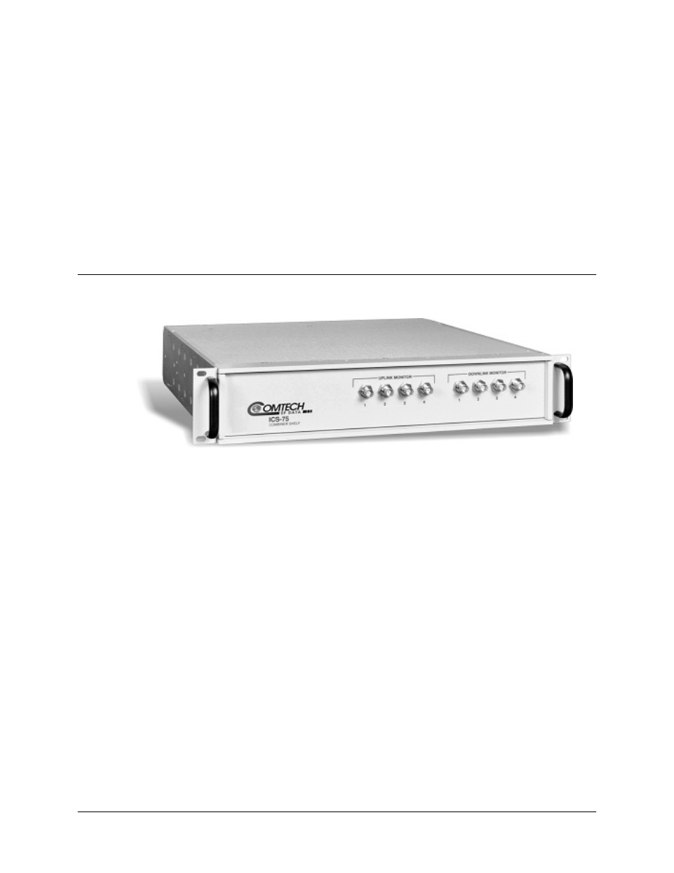
Figure 1-1. ICS-75 Integrated Combiner Shelf
The ICS-75 Combiner Shelf, shown in Figure 1-1, organizes the mass of cables and
individual splitter/combiners usually associated with earth station IF racks into one
convenient package.
Housed in a 2RU (3.5”) high, 19” rack-mountable chassis, the ICS-75 is composed
entirely of passive components, and therefore requires no AC power input.
Operating in the IF frequency range of 50 to 180 MHz, the ICS-75 consists of four IF
combiners and four IF splitters built into the same chassis:
•
Each uplink channel may optionally have four, six, or eight inputs.
•
Each downlink channel may optionally have four, six, or eight outputs.
Each channel has a monitor port available to sample the combined port. The monitor
ports are location on the front panel, while all inputs and outputs are located on a
logically arranged rear panel, eliminating confusion and greatly easing equipment
installation and rack configuration.