2 downlink monitor, 4 connector pinouts, Rear panel – Comtech EF Data ICS-75 User Manual
Page 22: 4 connector pinouts 3.4.1 rear panel
Advertising
ICS-75 Integrated Combiner Shelf
Revision 5
Cable Connections
MN/ICS75.IOM
3–4
3.3.3.2 Downlink
Monitor
These four outputs provide a means to check the received IF signals. Each sample is
taken by a 20 dB directional coupler.
3.4 Connector
Pinouts
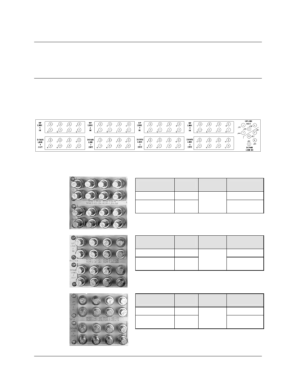
3.4.1 Rear Panel
Figure 3-3. Rear Panel Connector Schematic
Name
Ref. Des.
Connector
Type
Function
UPLINK 1 IN
J1-J8
Uplink IF input
DOWNLINK 1
OUT
J51-J58
BNC
Downlink IF
output
Name
Ref. Des.
Connector
Type
Function
UPLINK 2 IN
J11-J18
Uplink IF Input
DOWNLINK 2
OUT
J61-J68
BNC
Downlink IF
Output
Name
Ref. Des.
Connector
Type
Function
UPLINK 3 IN
J21-J28
Uplink IF input
DOWNLINK 3
OUT
J71-J78
BNC
Downlink IF
output
Advertising