1 redundant plate installation, 4 1:1 redundant plate installation – Comtech EF Data HPCST-5000 User Manual
Page 100
Advertising
Redundant System Installation
High-Power C-Band Satellite Terminal
4–18
Rev. 0
4.3.4
1:1 Redundant Plate Installation
Note: Refer to Section 8, Figure 8-2 for cabling configuration.
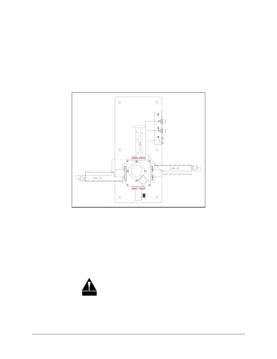
The 1:1 redundant plate is shown in Figure 4-2 as follows:
Figure 4-2. 1:1 Redundant Plate
Install the 1:1 redundant plate as follows:
1. Mount the 1:1 redundant plate to the antenna.
Note: The type of mounting is determined by the brand of antenna on which the
equipment will be installed.
2. Remove the plastic cover from the RF IN connector of the redundant plate.
CAUTION
After removing the protective cover, ensure that no foreign material
or moisture enters the 1:1 redundant plate’s waveguide.
Advertising