Cabling, Abling – Comtech EF Data SDM-2020 User Manual
Page 34
SDM-2020 Satellite Modulator
Revision 7
Installation
MN/SDM2020M.IOM
3-4
3.2.1 C
ABLING
IMPORTANT
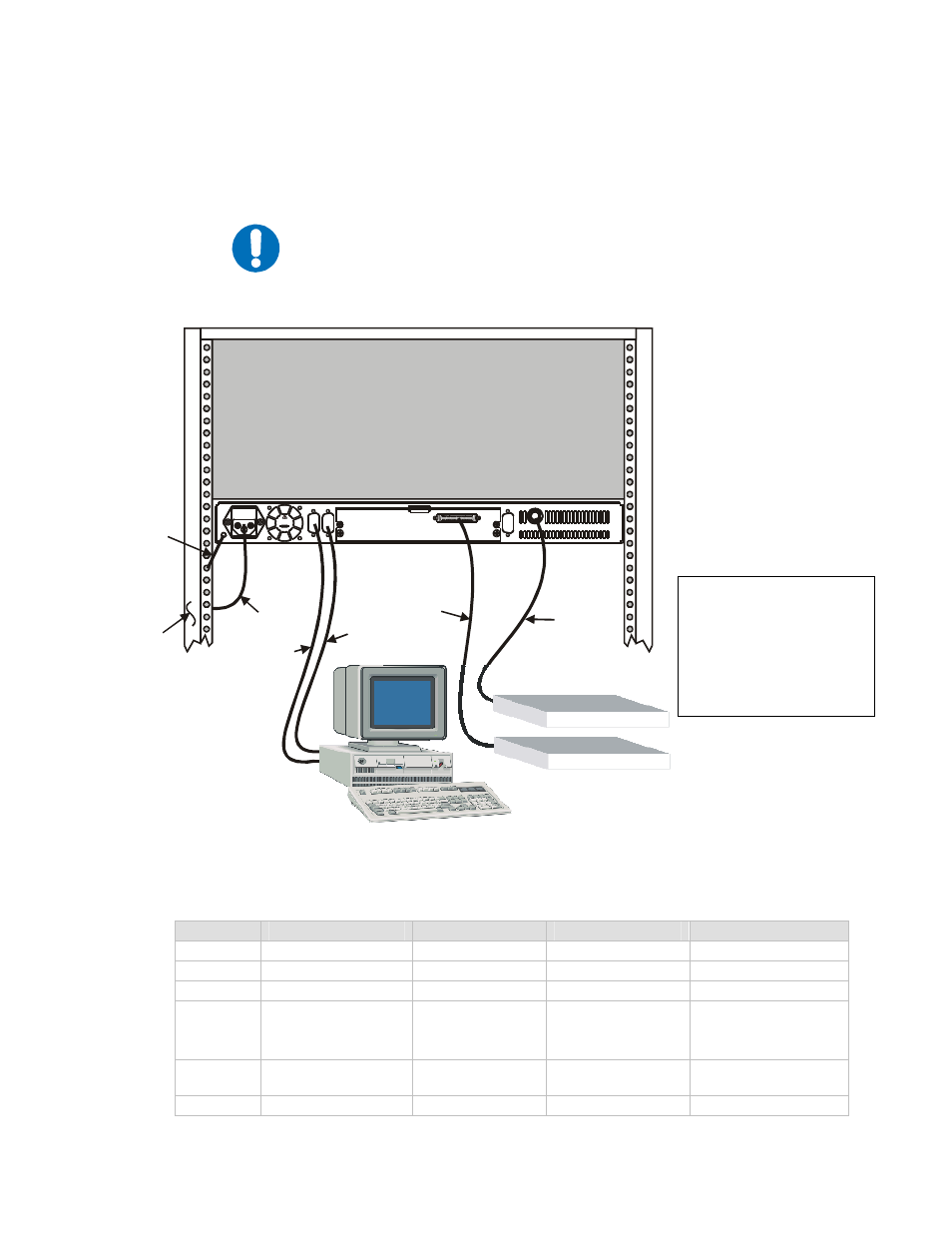
The following cabling instructions are generic. Comtech EF Data realizes
there are several different cabling applications for the SDM- 2020
Modulator, however, this manual cannot illustrate or described the
various installation configurations.
Figure 3-2. Rear View of SDM-2020M Rack Installed
Item #
Cable
From
To
Comment
1
Prime Power Cord
I.E.C
Rack Power Source
3-Pong Power Cord
2
Remote
J1
EXT PC Terminal
9-pin D
3
Fault
J2
EXT PC Terminal
9-pin D
4
Data Interface,
Customer Select
Interface
JX SERIAL
JX PARALLEL
JX AUX
Cissco router or
equivalent
Refer to Chapter 6
Data Interfaces
5 IF
Output
CP1
Upconverter or
RF Terminal
BNC
6
Ground
#10-32 Stud
Rack Equipment
Lengend
Prime Power Cord
Remote Ribbon Cable
Fault Cable
Data Interface
IF Output
Ground
J1
J2
T
E
T
O
M
R
E
A
U
L
F
J21
J21
T
R
O
I
N
M
M
O
RF 1
1.5A 50-60Hz
100-240V ~
T2A, 250V
ECL / HSSI INTERFACE
J3
Up Converter
Router
1
2
3
4
5
6
Back of
Rack