External connections, Chapter 4. external connections, Xternal – Comtech EF Data SDM-2020 User Manual
Page 37: Onnections
Advertising
4- 1
Chapter 4. EXTERNAL CONNECTIONS
4.1
E
XTERNAL
C
ONNECTIONS
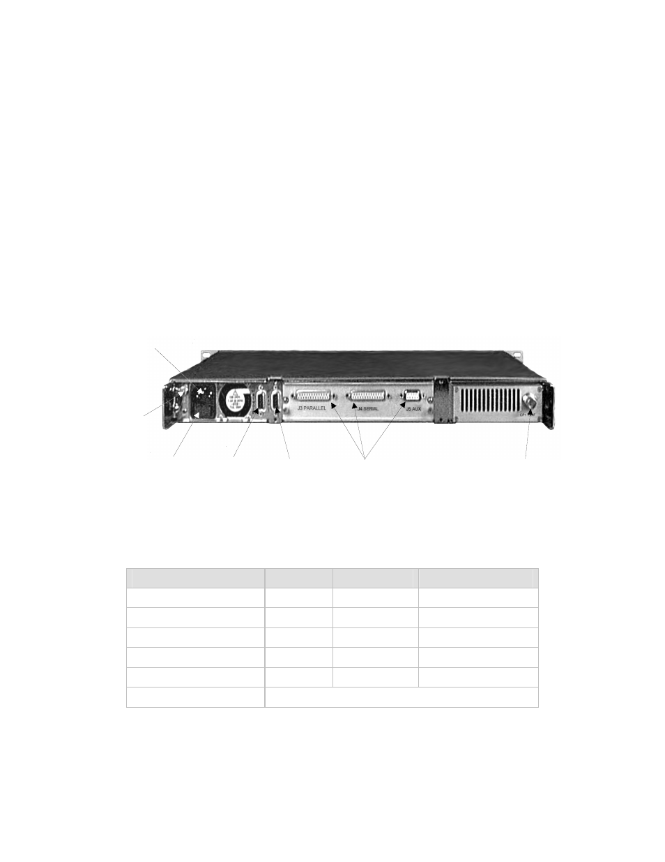
The connectors for the main unit are shown in Figure 4-1 and identified in Table 4-1.
The connectors for each plug-in data interface are described in their applicable chapters.
PRIME
POWER
GROUND
J1 REMOTE
FUSE HOLDER
J2 FAULT
DATA INTERFACE CONNECTIONS
CP1 TX-IF
Figure 4-1. Rear Panel
Table 4-1. Rear Panel Connectors
Name
Ref. Desig.
Type
Function
Remote
J1
9-pin D Female Remote control (M&C)
Fault
J2
9-pin D Female
Faults status relays
IF Output
CP1
BNC-Female
Transmit IF output
Prime Power
I.E.C
Standard
AC Power Input
GND
None
#10-32 Stud
Chassis Ground
Data Interface Connectors See applicable chapter.
Advertising