Crest Electronics CRE57000 TRAIN ENGINEER REVOLUTION MANUAL User Manual
Page 33
33
line with the positive power connection to prevent damage to both the Revolution
TE and the battery pack. Solder the Negative side of the battery pack to TRK-.
Solder the Positive side of the battery pack to TR+.
Connecting the Headlights: The headlights will most likely require rewiring. All
of the wiring to the headlights MUST be isolated from all other wiring. See the
following wiring diagrams to connect the headlights in your locomotive.
HD2 is soldered to the Front headlight and is the negative power lead for the front
headlight. HD1 is soldered to the rear headlight and is the negative power lead for
the rear headlight. HD COM is soldered to both the Front and Rear Headlights
and is the positive power lead for both front and rear headlights.
Remaining connections: You can now connect any remaining lights and smoke unit,
that you want to control manually, to the power source (track pickups or battery)
and control switches. If you want to control these functions remotely please see
the Auxiliary Wiring Harness instructions (page 18) and Smoke Control Board
instructions (page 19) for guidance.
4) SECURING THE Revolution TE. The Revolution TE should be located so that it
is secure and insulated from any metal inside the locomotive. The Revolution TE
can be attached to the shell or interior floor of the locomotive with double stick
foam tape. Or the circuit board on the wire harness can be glued to the shell or
interior floor, using silicone adhesive or hot melt glue.
5) FINISHING THE INSTALLATION. Refer to Step 4 (beginning on page 9)
in the Receiver Installation instructions of this Manual to continue the receiver
installation.
6) PROGRAMMING THE LOCOMOTIVE. Refer to Page 13 to program your
locomotive in the Revolution TE Transmitter.
Note: The Revolution TE Receiver antenna may be extended when installed in
a locomotive which has an all metal body. Generally, the exposed portion of the
antenna (outside of the metal body) should be equal in length to the antenna supplied
on the receiver and located as high as possible on the locomotive. You may have
to make adjustments to your antenna for best reception. DO NOT MODIFY THE
ANTENNA WHEN INSTALLING THE TE RECEIVER IN PLASTIC BODY
LOCOMOTIVES.
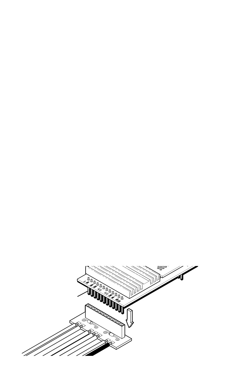
Receiver
12 Pin Header