Daktronics DF-1050/1051/1052/1053 User Manual
Page 25
Electrical Installation
3-7
Standard Fiber Optic Setup
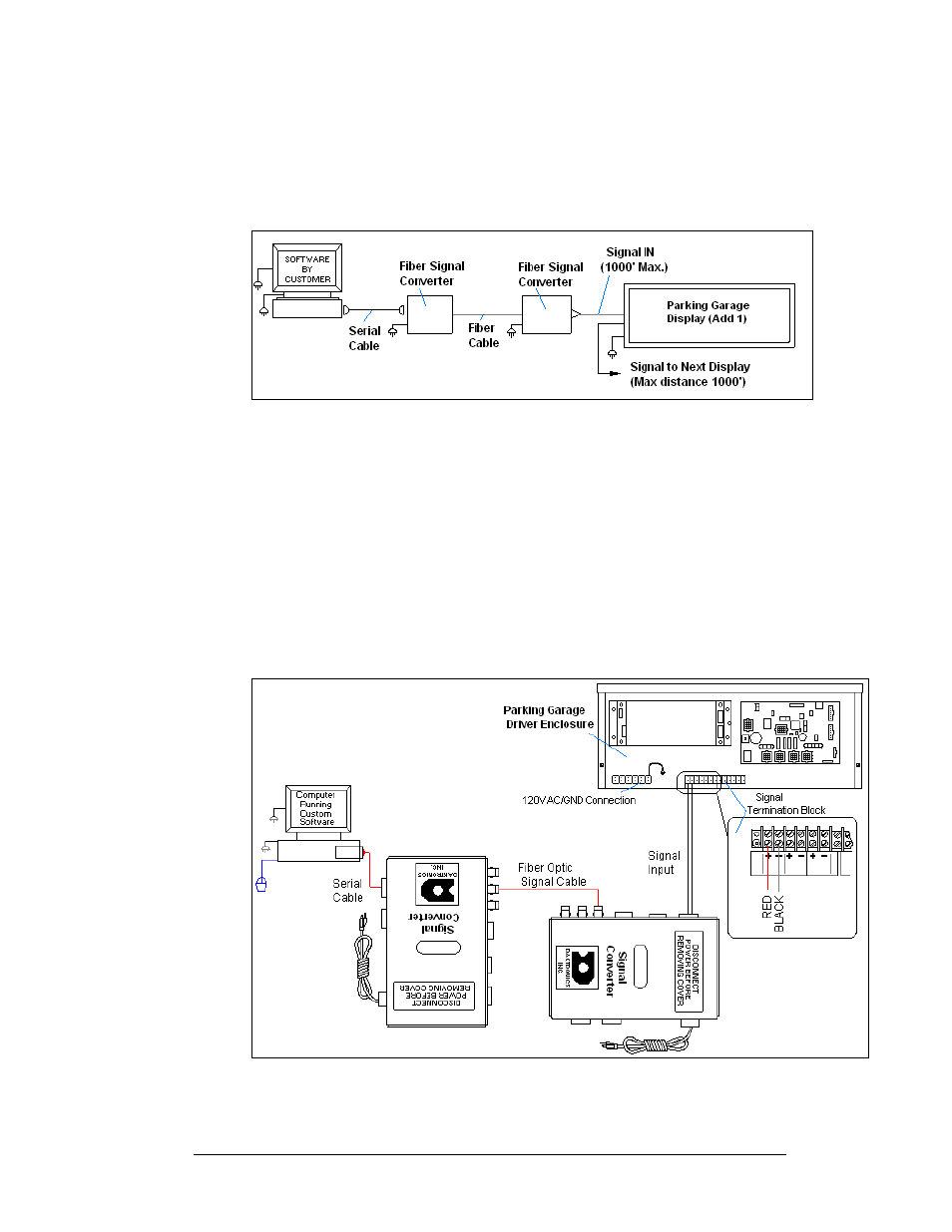
A standard fiber optic connection requires a computer connected to a signal
converter, a fiber optic cable connected to a second signal converter, and then signal
cable connected to the display. Refer to Figure 12 and Drawing A-196787 for
system layout.
1. Using a DB9M to DB9F serial cable (W-1267) connect from the computer
to J1 on the fiber optic signal converter (0A-1065-1074).
2. Connect from J5 (TX) on the first signal converter to J4 (RX) on the second
signal converter. The maximum distance is 4000 ft.
3. Using a two-conductor, 22 AWG, shielded cable (W-1077) to connect from
TB1 on the signal converter to the terminal block in the display. The
maximum distance is 1000 ft.
4. Connect from pin 1 of TB1 of the second fiber optic signal converter to pin
1 of the terminal block in the display, and pin 2 to pin 2.
5. Refer to Figure 13 and Drawing A- 191943 for the display connections.
Figure 12: Standard Fiber Optic Layout
Figure 13: Stand Fiber Optic Signal Connections