4 troubleshooting – Daktronics DF-1050/1051/1052/1053 User Manual
Page 33
Maintenance and
Troubleshooting
4-5
Light Sensor Installation
Reference Drawings:
Light
Sensor
Installation, G3........................................ Drawing A-183775
System Riser; Light Sensor ......................................... Drawing A-210516
Mechanical Specification Drawings ......................... Refer to Appendix A
Displays in the DataMaster series use a light sensor to regulate sign dimming
functions. Use Drawing A-183775 and the following instructions to replace the light
sensor in your DataMaster Parking Garage display.
If the sign or sign system has more than one display and is being controlled by the
DM-100 controller or using software based on the Daktronics Venus 1500 protocol,
install the light sensor in the host display only. If the system is controlled by
software based on the Daktronics multi-drop protocol, refer to Drawing A-210516
for wiring options.
1. Open the display as described in
Section 4.2. The light sensor will
usually be mounted to the panel
between the first and second digits.
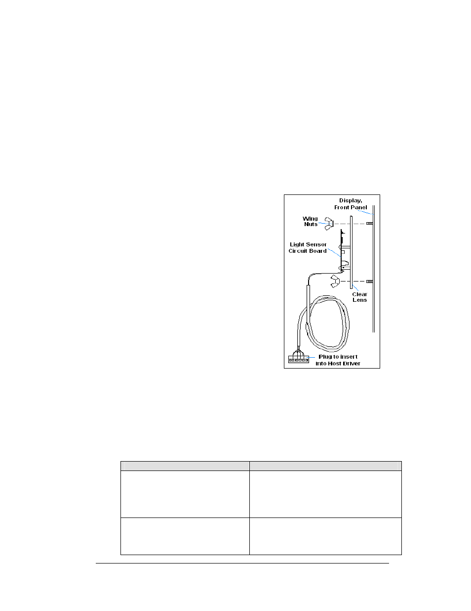
2. Locate and remove the
5
/
8
" plastic plug
from front panel of the display, as
shown in Figure 22.
3. There are two 6-32 studs above and
below the plughole. The internal light
sensor assembly (Daktronics part #0A-
1279-0203) is positioned on the studs,
with the clear lens toward the front of
the cabinet and the cable at the bottom.
Secure the sensor with the plastic wing
nuts provided with the assembly kit.
4. Route the signal cable to the driver and
insert the 6-position plug into the
mating jack (TB1) on the driver.
5. Close the display face panel.
4.4 Troubleshooting
This section lists some symptoms that may be encountered with the display. For
these symptoms, possible cause and corrective actions are indicated. This list does
not include every possible problem, but does represent some of the more common
situations that may occur.
Symptom/Condition
Possible Cause or Corrective Action
Entire display fails to work
• Check for proper line voltage at termination
panel
• Check connections from power supply to
driver (J17)
• Check power LED on driver
Cannot communicate with display via
current loop
• Check connections at J-box and display
• Make sure DataMaster is receiving power
• Check serial cable from DataMaster to j-
box
Figure 22: Light Sensor
Installation