Section 2: setup, 1 power connection, 2 video camera connection – Daktronics All Sport CG User Manual
Page 9: Section 2, Setup, Power connection, Video camera connection
Setup
3
Section 2:
Setup
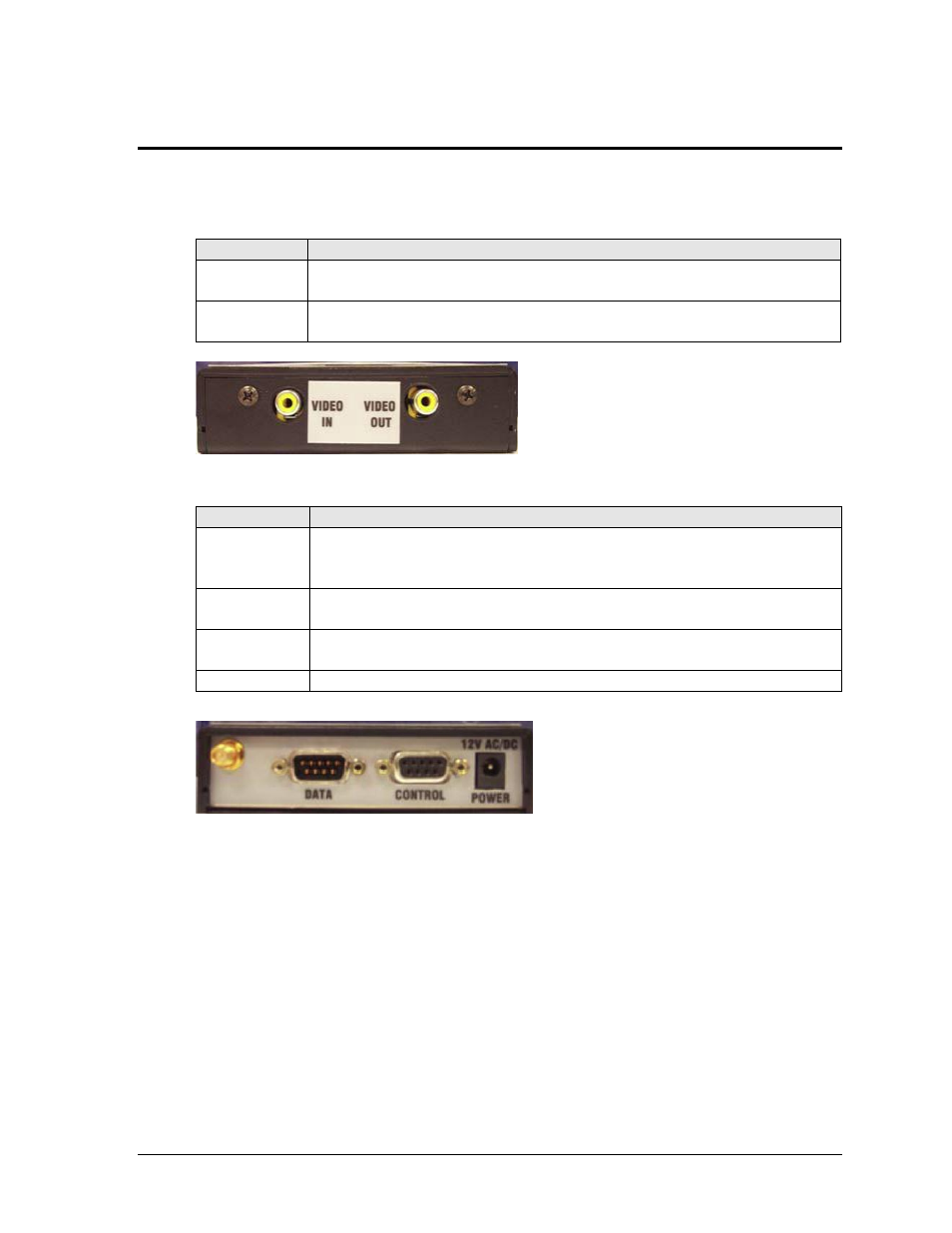
Use the tables and figures below to identify the various jacks that are used to connect
components to the All Sport CG:
Jack
Description
VIDEO IN
(Composite)
Receives the video feed from camera or other source (analog NTSC Only)
VIDEO OUT
(Composite)
Sends the video feed with overlaid game-in-progress information to
recording device (analog NTSC Only)
2.1 Power Connection
The All Sport CG receives power from a standard 120 VAC outlet via a 12 VAC transformer
to the POWER jack on top of the All Sport CG. Plugging in and disconnecting the transformer
will power the unit on and off.
2.2 Video Camera Connection
The connection between the camera or video source and the All Sport CG is always via wire.
The analog NTSC video signal is carried via an RCA cable connection from the VIDEO OUT
jack on the video camera to the VIDEO IN jack on the bottom panel of the All Sport CG.
Figure 3: All Sport CG, Bottom View
Jack
Description
Antenna
Radio Unit Only. Receives game-in-progress information from the All
Sport controller via wireless radio signal (both All Sport CG and control
console must be equipped with optional radio kits)
DATA
(DB9-M)
Receives the game-in-progress information from the All Sport controller
via a direct wire connection
CONTROL
(DB9-F)
Receives firmware upgrade information; also used to output TV data feeds
and upload custom graphics (see Appendix B)
POWER
Receives power via 12 VAC transformer
Figure 4: All Sport CG, Top View