Chapter 2 - hardware installation, System board layout, Hardware installation – DFI LR102-B18D/B18S User Manual
Page 16: Inte l ich8m inte l, Mini pci e, Battery, Usb 0-1 lan 1 com1, Compactflash
Advertising
16
2
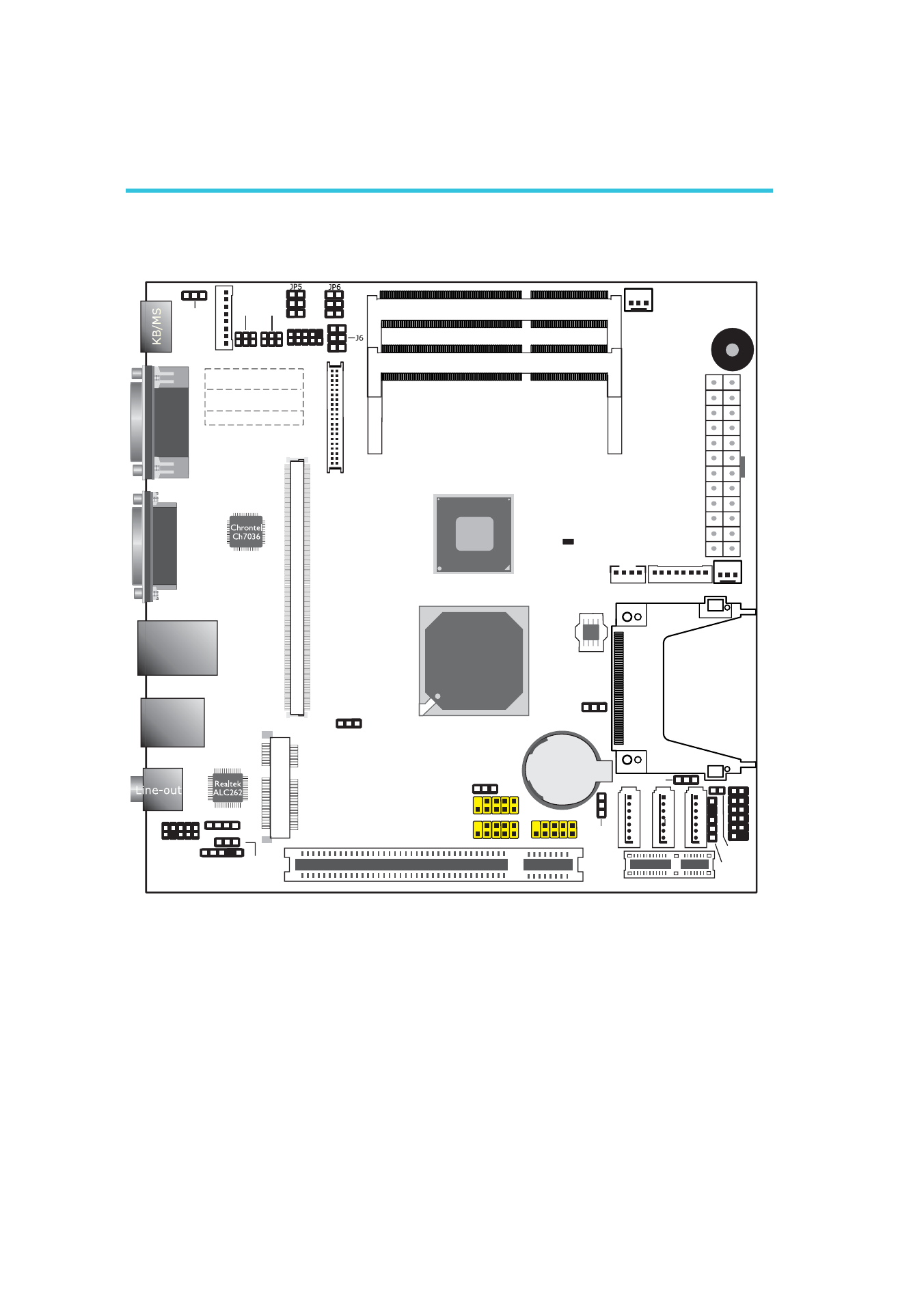
Hardware Installation
System Board Layout
Chapter 2 - Hardware Installation
CPU fan
1
1
1
2
9
USB 6-7
1
2
9
USB 2-3
1
2
9
USB 4-5
USB 0-1
LAN 1
COM1
System fan
1
SPI
PCIE x1
PCI x1
Front
panel
1 2
CompactFlash
1
13
12
24
AT
X
p
o
w
er
DDR3_2 DIMM2
DDR3_1 DIMM1
1
2
5
6
1
2
5
6
1
2
5
6
1
2
10
LVDS LCD
panel
40
39
2
1
1
DIO power
DIO
1
1
SA
TA
2
SA
TA
1
SA
TA
0
Battery
1
1
1
Daughterboar
d
C
onnector
1
2
9
10
1
1
1
1
1
Inte l
ICH8M
Inte l
Atom
1
1
1
1
1
VGA
Mini
PCI
e
CD-in
LVDS Inverter
Front audio
S/PDIF
Panel power select ( )
J6
COM 2
Chassis
intrusion
SMBUS
connector
S/PDIF
(JP1)
PS/2 power
select (J
)
P2
COM1 (
), COM2 (JP4)
RS232/422/485 select
JP3
JP3
JP4
COM1 (JP5), COM2 (JP6)
RS232/Power select
USB 0-1 power
select (J
)
P7
USB 2-5 power
select (J
)
P8
USB
6
-7p
o
w
er
select
(J
)
P10
Clear CMOS
(JP9)
Power-on
select (
)
JP11
Standby
Power LED
1
1
2
2
Advertising
This manual is related to the following products: