Caster wheel spacer height adjustment, Cord head height adjustment – DR Power Tow-Behind All Terrain User Manual
Page 11
CONTACT US AT www.DRpower.com 11
Setting the cutting height of the Cords is done by adjusting the Cord Head
location and/or by rearranging the Spacers of the Caster Wheel Assembly. The
Spacers are 1/2" thick to provide height adjustments in 1/2-inch increments.
Changing the Cord Head location from below the molded Spacer to above it will
change the height by 1-1/2" so the cutting height with the Cord Head at its
lowest setting would be 3" with all Spacers on top of the Caster Bracket, to
approximately 6" when all Spacers are below the Caster Bracket (Figure 10). The
range with the Cord Head at its highest setting would be 4-1/2" with all Spacers
on top of the Caster Bracket, to approximately 7-1/2" when all Spacers are below
the Caster Bracket. The Trimmer must always be set level by adjusting the Tow
Hitch after Caster Wheel Spacer locations are changed.
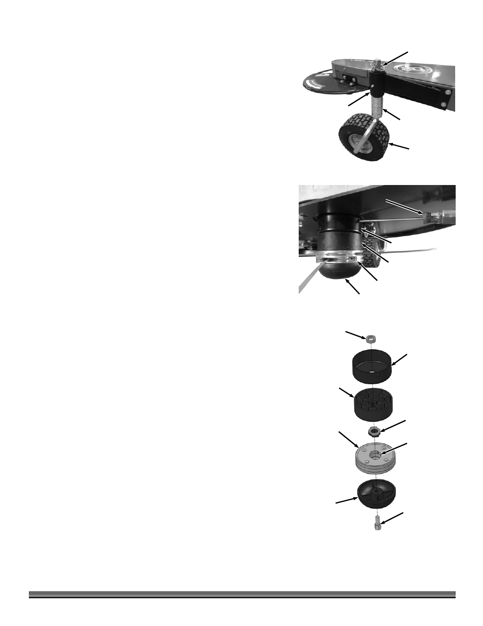
Caster Wheel Spacer Height Adjustment
1. Remove the Hitch Pin and remove the Caster Assembly from the Bracket
(Figure 10).
2. Insert Spacers onto the Caster Shaft depending on the height desired and
install the Caster Shaft into the Bracket.
3. Install remaining Spacers and secure with the Hitch Pin.
Cord Head Height Adjustment
Note: The Cord Head can be located above or below the Molded Spacer giving
you a 1-1/2" range in trimming height. The following steps show moving the
Cord Head from below the Molded Spacer to on top of the Molded Spacer.
Tools and Supplies Needed:
Phillips head Screwdriver with at least a 6" shank
Gloves
1. Align the hole in the Anti Wrap Canister with the hole in the internal housing
at the location shown (Figure 11).
2. Insert a Philips Head Screwdriver into the hole in the Anti Wrap Canister and
the hole in the internal Housing.
3. Rotate the Mow-Ball
®
Assembly until the Screw Driver slides into a hole in
the shaft, locking it into place.
4. Looking down at the top of the Frame, turn the Mow-Ball
®
clockwise until it
unscrews completely from the Bearing Housing.
Note: If the Mow-Ball
®
continues to turn, but does not come off, check that you
locked the Screwdriver into the shaft. If the Mow-Ball will not turn by hand a
9/16" Socket can be used on the Bolt (inside the bottom of the Mow-Ball) to
loosen it. You may need to clean grass or debris out of the recess first.
5. Slide the Cord Head, Adapter and Molded Spacer off the Shaft (Figure 12).
6. The Anti-Wrap Can and Spacer should remain on the Shaft with the
Screwdriver.
7. Make sure the Adapter is inserted into the top of the Cord Head as you
install the Cord Head onto the Shaft.
8. Install the Molded Spacer onto the Shaft.
9. Place the head of the Mow-Ball
®
Bolt so it is sitting inside the hex cavity at
the bottom of the Mow-Ball
®
.
10. Looking down at the top of the Frame, hold the Bolt Head in place with your
finger and turn the Mow-Ball
®
counterclockwise to start the Bolt into the Shaft.
Caster Wheel
Figure 10
Spacers
Hitch Pin
Caster Bracket
Mow-Ball
®
Figure 12
Mow-Ball
®
Bolt
Cord Head
Adapter
Molded Spacer
(can be above
or below Cord
Head)
Anti-Wrap Can
Spacer
Adapter Hole
(facing up)
Cord Head
Figure 11
Molded Spacer
Anti-Wrap Can
Mow-Ball
®
Screw Driver