Adjusting the tow bar offset, Hitching the trimmer to the tow vehicle, Leveling the trimmer – DR Power Tow-Behind All Terrain User Manual
Page 12
12
DR
®
7.25 ALL-TERRAIN TRIMMER/MOWER
Always make sure you remove the screwdriver from the head assembly when
finished. Failure to remove the screwdriver could cause injury when the head
assembly is engaged.
11. Tighten the assembly securely by turning the Mow-Ball
®
counterclockwise
when looking down on the top of the Frame (Figure 13).
12. Remove the Screwdriver.
Adjusting the Tow Bar Offset
Tools Needed:
9/16" Wrench
Note: This procedure is easier with the Trimmer disconnected from the Tow Vehicle.
1. Disconnect the Trimmer from the Tow Vehicle.
2. Remove the front Bolt using a 9/16" Wrench (Figure 14).
3. Loosen the rear Bolt using a 9/16" Wrench only enough to allow the Tow Bar
to rotate.
4. Rotate the Tow Bar to align the holes for the desired offset (Figure 15).
5. Reinstall the front Bolt and tighten both Bolts using a 9/16" Wrench.
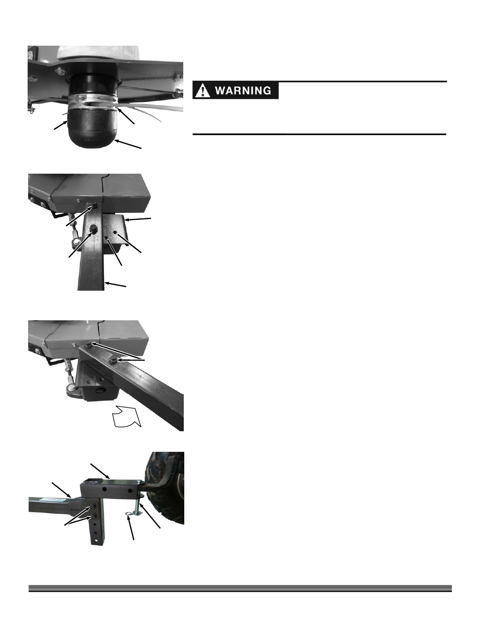
Hitching the Trimmer to the Tow Vehicle
1. Position the Tow Hitch onto the Tow Vehicle Hitch and secure with the
clevis Pin, Flat Washer and Hitch Clip (Figure 16).
2. If your Tow Vehicle Hitch will not fit adequately into the Tow Hitch opening,
you can mount the Tow Bar on top of the Tow Vehicle Hitch.
Note: The preferred method is to locate the Tow Vehicle Hitch inside the Tow Hitch
opening.
Leveling the Trimmer
Tools Needed:
Two 9/16" Wrenches
Note: When cutting height is set by the Caster Wheel Spacers and/or the Cord
Head location you must also level the machine by adjusting the Tow Hitch height.
1. Remove the two Bolts and Locknuts that secure the Hitch to the Tow Bar
and position the Hitch at the desired setting to level the machine (Figure
16). Ensure the bottom of the Tracking Wheel Support is level with the
ground and has a minimum clearance of 4-1/2".
2. Install the two Bolts and Locknuts and tighten with two 9/16" Wrenches.
Note: The Tow Hitch can be rotated to position the Clevis Pin holes at the top or
bottom depending on how much adjustment you need to adjust the Tow Bar to level
the machine.
Cord Head
Figure 13
Mow-Ball
®
Molded
Spacer
Figure 15
Flange Bolts
and Lock
Washers
Pivot
Assembly
Figure 14
Tow Bar Assembly
Front Flange
Bolt and
Lock Washer
Rear Flange
Bolt and
Lock Washer
40° Offset
20° Offset
Tow Hitch
Figure 16
Clevis Pin
Hitch Clip
Tow Bar
Bolts and
Locknuts